


 307 / 582

BETA Protecting
Overvoltage Protection Devices
Configuration
6/21
Siemens ET B1 · 10/2008
6
*
You can order this quantity or a multiple thereof.
Coordinated use of lightning and surge arresters
In practice, arresters of the different requirement categories are
switched in parallel. Due to their different operating characteristics,
discharge capacity and protection tasks, the different arrester
types must be installed in the system so that the nominal values
of the individual devices are not exceeded, thus ensuring
consistent protection.
In order to enable subsequent coupling, we recommend inserting
an additional type 2 surge arrester every 10 m.
In order to ensure that a surge current always switches to the
nearest upstream arrester – if there is a risk that the surge current
could overload the respective arrester – it is necessary to take
energetic considerations into account.
This is called "energetic coordination" and must be established
between type 1 and type 2 arresters, as well as between type 3
arresters.
In the past, this was achieved through the laborious and costly
installation of decoupling reactors or sufficiently long cable
lengths. However, thanks to modern tripping technology, this is
no longer necessary.
Follow current discharge capacity
The data for the follow current discharge capacity of lightning
arresters indicates the maximum line current that the arrester is
capable of interrupting by itself without needing help to extinguish
the fault from an upstream protective device, such as a fuse or
miniature circuit breaker. The follow current is a result of the short
circuit produced briefly by the lightning arrester to discharge the
lightning current. The follow current is therefore a short-circuit
current and has a frequency of 50 Hz.
If the maximum permissible short-circuit current of the plant is
smaller than the maximum follow current that can be extinguished
by the SPD, no upstream protective device is required. If this is
not the case, a fuse or miniature circuit breaker is required.
SPD with miniature circuit breakers and fuses
Miniature circuit breakers or fuses should perform the following
tasks:
•
Protect the SPD from overload in the event of overcurrent
•
Ensure plant availability
•
Help suppress system follow currents
Fuses or miniature circuit breakers therefore ensure that the max.
permissible peak current
I
p max
and the maximum permissible
energy value
I
2
t
max
of the SPD are not exceeded. This prevents
damage to the SPD.
We recommend using fuses rather than miniature circuit breakers
as they have a smaller voltage drop and ensure better protection.
A distinction is generally made between 2 different connection
types:
•
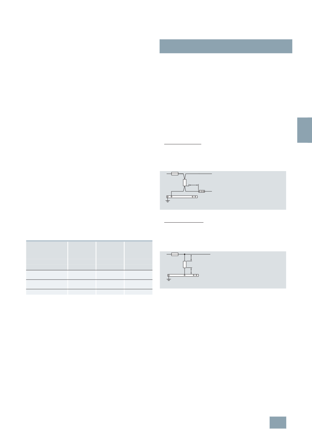
Series connection:
The installation is protected over the protective device that is
fitted in the power distribution as standard. The SPD is protected
over the plant fuse installed in the system. If this fuse is tripped
because the SPD is overloaded, the plant is disconnected
from the supply by the fuse or miniature circuit breakers.
Recommended max. cable length for series connection
•
Parallel connection:
the protective device is located in the connecting cable of the
SPD. If the miniature circuit breaker or fuse is tripped, the
power supply of the plant is maintained. In this case, we
recommend using a signaling device to signal that the
overvoltage protection function has been disconnected from
the supply and is therefore no longer effective.
Recommended max. cable lengths for parallel connections
Your configuration should therefore take into account the values
for the maximum permissible arrester back-up fuses stipulated
in the technical specifications.
Generally speaking, a series connection is always preferable to
a parallel connection. This connection is particularly suitable for
reducing additional voltages on surge current cables.
Devices
Maximum
permissible
energy value
Maximum
permissible
peak current
value
No protection
necessary if
I
2
t
max
I
p max
I
cc rms
kA
2
s
kA
kA
Lightning arresters,
type 1
180
12
Up to 50
Combination surge
arresters, type 1 and 2
180
12
Up to 25
Surge arresters, type 2 180
12
Up to 25
PAS
PE
L
I2_13776a
≤ 0,5m
S
P
D
DIN V VDE V 0100-534;
IEC 60364-5-534
PAS = equipotential bonding strip
PAS
L
I2_13777a
b
a
S
P
D
DIN V VDE V 0100-534 (for a, b 0.5 m);
IEC 60364-5-534 (for a + b 0.5 m);
CEI 81-8:2002-02 (for a + b 0.5 m)
PAS = equipotential bonding strip
© Siemens AG 2008