


 303 / 582

BETA Protecting
Overvoltage Protection Devices
Link rails
6/17
Siemens ET B1 · 10/2008
6
*
You can order this quantity or a multiple thereof.
■
Overview
Link rails let you combine 1-pole surge arresters to create com-
plete solutions for multiphase systems.
■
Benefits
These link rails allow cable lengths to be reduced to a minimum
and save time during mounting.
■
Technical specifications
■
Selection and ordering data
■
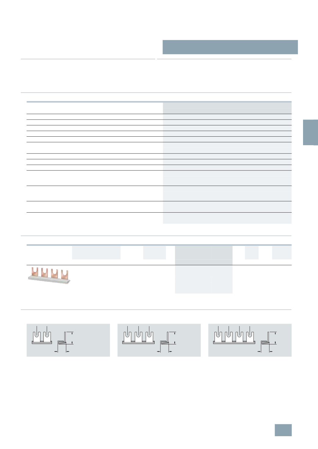
Dimensional drawings
Link rails
5
SD7 490-2, 5SD7 490-3, 5SD7 490-4
Standards
EN 60439-1 (VDE 0660-500:2005-01)
Busbar material
SF-Cu F 24
Partition material
Plastic, cycolor 3600 heat-resistant 90 °C
Busbar cross-section
mm
2
16
Rated operational voltage U
c
V AC 400
Rated current
I
n
•
Cross-section 16 mm
2
A
80
Rated impulse withstand voltage U
imp
kV
4
Test pulse voltage (1.2/50)
kV
6.2
Rated conditional short-circuit current
I
cc
kA
25
Resistance to climate
•
Constant atmosphere acc. to DIN 50015
23/83; 40/92; 55/20
•
Humid heat (acc. to IEC 68, Part 2-30)
28
cycles
Insulation coordination
acc. to VDE 0110-1 April 1997 (IEC 664)
•
Overvoltage category
III
•
Degree of pollution
2
Maximum busbar current
I
s
/
phase
•
Cross-section 16 mm
2
A
80
Maximum current in the arm
I
E
/
phase
•
Cross-section 16 mm
2
A
130
Version
Linking
sequence
Length
DT Order No.
Price
per PU
PG PU PS*/
P. unit
Weight
per PU
approx.
MW mm
Unit(s) Unit(s) kg
Link rails for the interconnection of single-pole
surge arresters, type 2
N
• 2-
pole
2
34
A
5
SD7 490-2
008 1
10/100 0.093
• 3-
pole
3
51.8
A
5
SD7 490-3
008 1
10/100 0.143
• 4-
pole
4
69.6
A
5
SD7 490-4
008 1
10/100 0.194
5
SD7 490-2
5
SD7 490-3
5
SD7 490-4
Pin spacing in MW.
Dimensions of side views in mm.
I2_13938
14,3
20,3
1
I2_13939
14,3
20,3
1 1
I2_13940
14,3
20,3
1 1
1
© Siemens AG 2008