


 296 / 582

BETA Protecting
Overvoltage Protection Devices
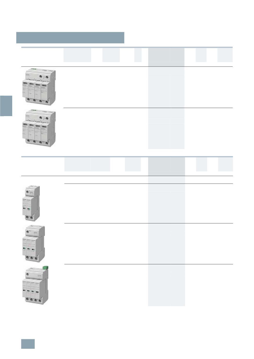
Surge arresters, type 2
6/10
Siemens ET B1 · 10/2008
6
*
You can order this quantity or a multiple thereof.
Version
Max.
continuous
voltage
U
C
Discharge
surge
current
I
n
/
I
max
MW DT Order No.
Price
per PU
PG PU PS*/
P. unit
Weight
per PU
approx.
V
kA
Unit(s) Unit(s) kg
• 4
P, plug-in, 3+1 circuit
For TN-S and TT systems
-
Without remote signaling 350 AC 20/40 4 A
5
SD7 464-0
008 1
1
0.433
-
With remote signaling 350 AC 20/40 4 A
5
SD7 464-1
008 1
1
0.443
• 4
P, plug-in, 4+0 circuit
For IT systems with N-conductor incorporated in
the cable
N
-
Without remote signaling 440 AC 20/40 4 A
5
SD7 485-0
008 1
1/44 0.445
-
With remote signaling 440 AC 20/40 4 A
5
SD7 485-1
008 1
1
0.455
Version
Discharge
surge
current
I
n
/
I
max
Mounting
width
DT Order No.
Price
per PU
PG PU PS*/
P. unit
Weight
per PU
approx.
kA
mm (MW)
Unit(s) Unit(s) kg
Surge arresters,
narrow design
• 2
P
For TN-S and TT systems
-
Without remote signaling 20/40 24 (1 1/3) A
5
SD7 422-0
008 1
1
0.220
-
With remote signaling
20/40 24 (1 1/3)
B
5
SD7 422-1
008 1
1
0.227
• 3
P
For TN-C systems
-
Without remote signaling 20/40 36 (2)
A
5
SD7 423-0
008 1
1
0.320
-
With remote signaling
20/40 36 (2)
B
5
SD7 423-1
008 1
1
0.330
• 4
P
For TN-S and TT systems
-
Without remote signaling 20/40 48 (2 2/3) A
5
SD7 424-0
008 1
1
0.408
-
With remote signaling
20/40 48 (2 2/3)
A
5
SD7 424-1
008 1
1
0.416
© Siemens AG 2008