


 291 / 582

BETA Protecting
Overvoltage Protection Devices
Combination surge arresters, type 1 and type 2
6/5
Siemens ET B1 · 10/2008
6
*
You can order this quantity or a multiple thereof.
■
Overview
Type 1 and type 2 combination surge arresters protect low-voltage
systems against the overvoltages and high currents that can be
triggered by direct lightning strikes. They are tested by
wave-shaped lightning impulses, 25 ... 100 kA with waveform
10/350
μs.
The protection level is lowered to 1.5 kV by the combination
surge arresters.
A thermal isolating arrester disconnector offers a high degree of
protection against overload.
All spark gaps are tripped. For this reason, decoupling reactors
are no longer required for the installation of overvoltage protection
devices.
■
Benefits
•
The rated arrester voltage is a uniform 350 V AC. This increases
safety in systems with extended voltage overshoots.
•
All combination surge arresters are fitted with a mechanical
fault indication that does not require an extra power supply.
•
The protective modules are plug-in versions. No dismantling
of electrical wires required when replacing the protective
modules. When taking insulation measurements, the protective
modules are simply removed in order to ensure disconnection
from the power supply.
•
The same type 2 overvoltage protective modules are used as
for the slim version of the surge arresters (5SD7 42.). This
simplifies stock-keeping.
•
All combination surge arresters have a remote signaling
contact, which signals if the device fails.
■
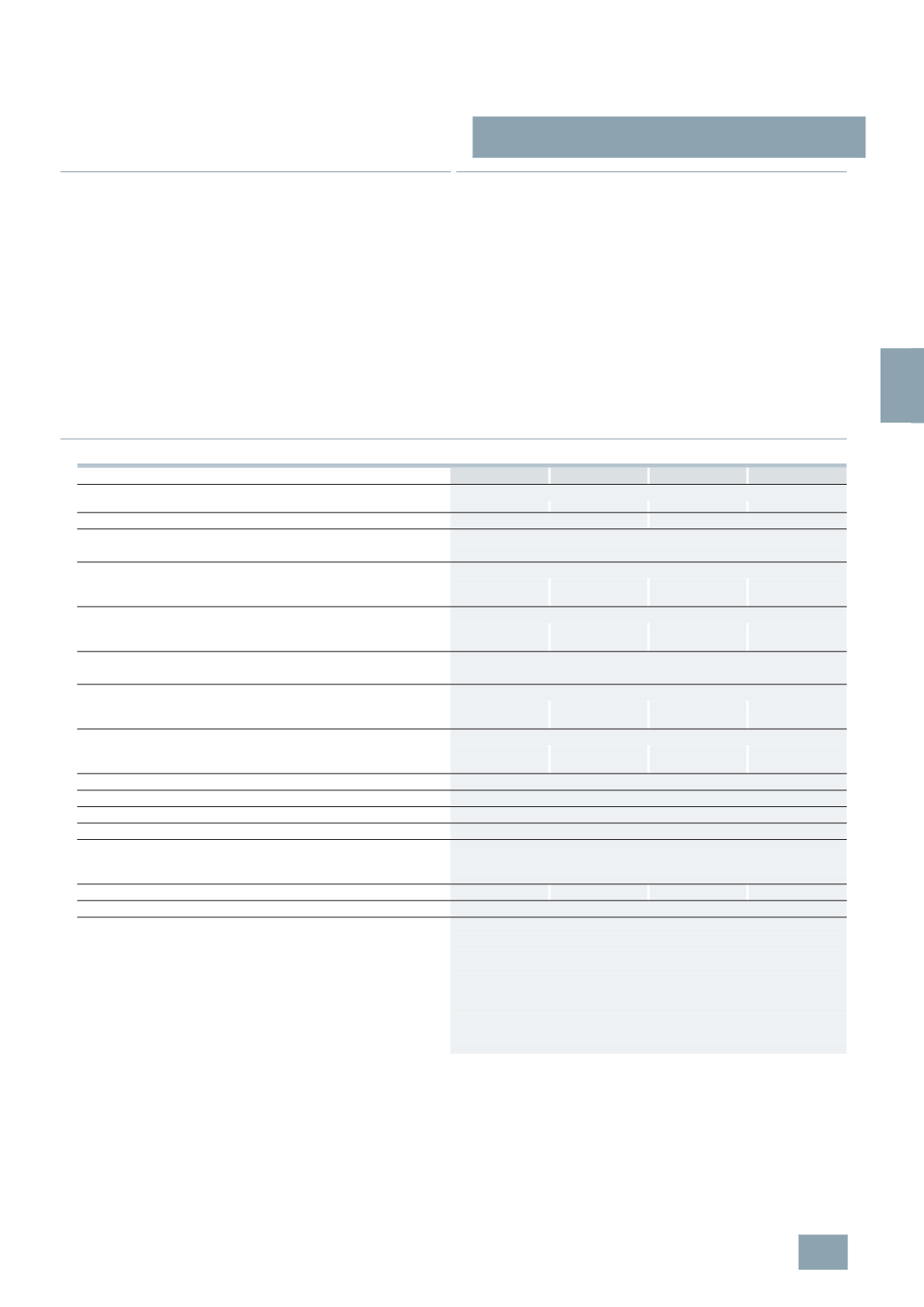
Technical specifications
5
SD7 441-1
5
SD7 442-1
5
SD7 443-1
5
SD7 444-1
Standards
IEC 61643-11; EN 61643-11
Approved acc. to
--
KEMA, UL/CUL KEMA, UL/CUL KEMA, UL/CUL
Rated voltage U
N
V AC 240
240/415
Rated arrester voltage U
C
•
L/N, N/PE, L/PEN
V AC 350
Lightning impulse current
I
imp
(10/350
s)
•
L/N or L/PEN, 1P/3P
kA 25
25/100
25/75
25/100
•
N/PE
kA --
100
--
100
Rated discharge surge current
I
n
(8/20
s)
•
L/N or L/PEN, 1P/3P
kA 25
25/100
25/75
25/100
•
N/PE
kA --
100
--
100
Protection level U
p
•
L/N, N/PE, L/PEN
kV
1.5
Follow current discharge capacity
I
fi
(
AC)
•
L/N or L/PEN
kA 25
25
25
25
•
N/PE
kA --
100
--
100
Response time t
A
•
L/N or L/PEN
ns
25
100
100
100
•
L-(N)-PE
ns
--
100
--
100
Required back-up fuse, max.
A
315
gL/gG
Short-circuit strength
with max. back-up fuse
kA
rms
25
Temperature range
°C -40 ... +80
Degree of protection
IP20, with connected conductors
Conductor cross-section
•
Finely stranded
mm
2
2.5 ... 25
•
Solid
mm
2
2.5 ... 35
Mounting width
Acc. to DIN 43880 MW 2
4
6
8
Visual function/fault indication
Yes
Remote signaling (RS)
Yes
•
Contact type
Floating CO contact (plug-in)
•
Operational voltage, max.
V AC 250
V DC 125
•
Operational current, max.
-
Resistive/inductive load
A AC 1/1
-
Resistive/inductive load
mA DC 200/30
•
Conductor cross-section
-
Finely stranded
mm
2
1.5
-
Solid
mm
2
1.5
© Siemens AG 2008