


 239 / 582

BETA Protecting
Low-Voltage Fuse Systems
3
NP LV HRC fuse switch disconnectors
3/89
Siemens ET B1 · 10/2008
3
*
You can order this quantity or a multiple thereof.
■
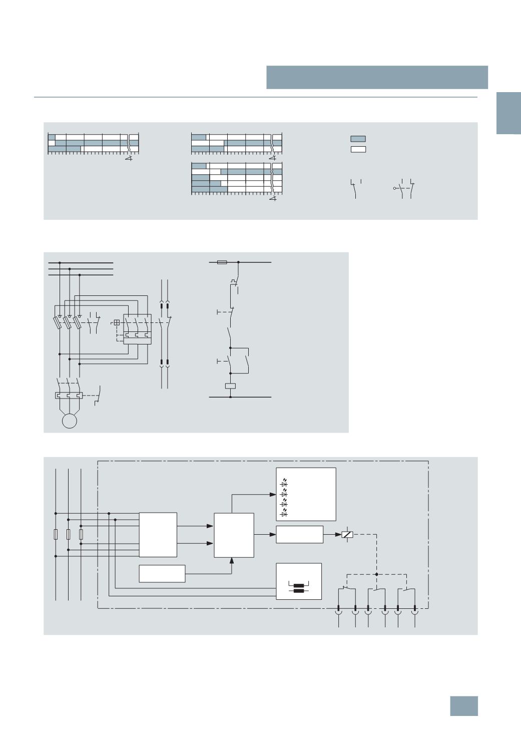
Schematics
Function auxiliary contact – main contact at SENTRON 3NP4 and 3NP5
SENTRON 3NP fuse switch disconnectors with fuse monitoring
(
with 3RV1 motor starter protector, with auxiliary switch 1 NO + 1 NC)
SENTRON 3NP5 fuse switch disconnectors with electronic fuse monitoring
42
0 5 10 15 20 61
°
13
14 22
0 5 10 15 20 77
°
NSE_00174e
0 5 10 15 20 70
°
21
1
Contact closed
Contact open
For 3NP40 1,
and 3NP4. 7
Auxiliary switch
On
Off
For 3NP5
13-14
21-22
3
NP52 60
3
NP54 60
13-14
21-22
3
NP50 60
3
NP53 60
(1
NO)
(1
NC)
(3
NO)
(3
NO)
(1
NO)
(1
NC)
(3
NO)
(3
NO)
On
Off
(3
NO)
(1
NC)
(1
NO)
1-4
1-2
3
NP40 1,
3
NP4. 7
Circuit diagram of main circuit
Circuit diagram of auxiliary circuit
Q1 = Fuse switch disconnector
Q2 = Motor starter protector
K1 = Contactor
S1 = ON pushbutton
S0 = OFF pushbutton
F1 = Overload relay
F2 = Control-circuit fuse
!
"
Block diagram
Version "A" (open-circuit principle):
Auxiliary switches only pick up if fuse faulty and voltage is applied.
Version "R" (closed-circuit principle):
Auxiliary contacts pick up as soon as voltage is applied and as long as fuses are intact.
1
11 12
23 24
33 34
6
5 4
3 2
BN
BU GY WH RD
BK
X1
L1 L2 L3
F1 F2 F3
L1' L2'
L3'
NSE0_00177a
Switching stage
Resistor
network
Parameterization
Synchroni-
zation
signals
Voltages
Micro-
controller
LED indication
Operation
Fault F1
Fault F2
Fault F3
Power
supply unit
Signal leads
© Siemens AG 2008