


 245 / 582

BETA Protecting
SITOR Semiconductor Fuses
SITOR, LV HRC design
4/5
Siemens ET B1 · 10/2008
*
You can order this quantity or a multiple thereof.
4
Size
I
e
U
e
Opera-
tional
classes
Breaking
I
2
t value
Power
loss
Varying
load
factor
DT Order No.
Price
per PU
PG PU PS*/
P. unit
Weight
per PU
approx.
A V AC
A
2
s
W WL
Unit(s) Unit(s) kg
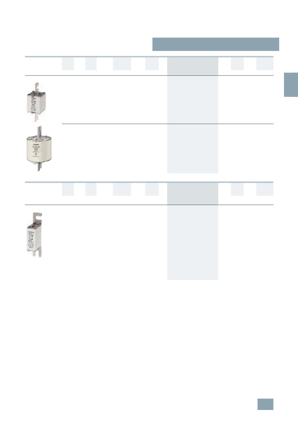
SITOR, LV HRC design
With slotted blade contacts for M12 screw fixing,
mounting dimension: 110 mm, or for installation in LV HRC
fuse bases or switch disconnectors
N
3
560 690
gR
890000 60
1.0
B
3
NE1 435-3
047 1
3
1.150
630
1390000 62
1.0
B
3
NE1 436-3
047 1
3
1.150
670
1640000 65
1.0
B
3
NE1 447-3
047 1
3
1.150
710
1818000 72
1.0
B
3
NE1 437-3
047 1
3
1.150
800
2475000 82
1.0
B
3
NE1 438-3
047 1
3
1.150
850
3640000 76
1.0
B
3
NE1 448-3
047 1
3
1.150
With slotted blade contacts with 2 M10 oblong slots for screw
fixing, or for installation in LV HRC fuse bases or switch
disconnectors
3
150 690
gR
17600 40
0.85
B
3
NC8 423-0C
047 1
3
0.940
200
38400 55
0.85
B
3
NC8 425-0C
047 1
3
0.940
250
70400 72
0.85
B
3
NC8 427-0C
047 1
3
0.940
350
176000 95
0.85
B
3
NC8 431-0C
047 1
3
0.940
500
448000 130 0.85
B
3
NC8 434-0C
047 1
3
0.940
Size
I
e
U
e
Opera-
tional
classes
Breaking
I
2
t value
Power
loss
Varying
load
factor
DT Order No.
Price
per PU
PG PU PS*/
P. unit
Weight
per PU
approx.
A V AC/
V DC
A
2
s
W WL
Unit(s) Unit(s) kg
SITOR, LV HRC design
With M8 bolt-on links, mounting dimension: 80 mm,
for screwing onto busbars
000
20 690/
700
gR
83
7
0.9
B
3
NE8 714-1
047 1
10 0.130
25
140
9
0.9
B
3
NE8 715-1
047 1
10 0.130
32
285
10
0.9
A
3
NE8 701-1
047 1
10 0.131
40
490
12
0.9
A
3
NE8 702-1
047 1
10 0.131
50
815
15
0.9
A
3
NE8 717-1
047 1
10 0.132
63
aR
1550
16
0.95
A
3
NE8 718-1
047 1
10 0.132
80
2700
18
0.9
}
3
NE8 720-1
047 1
10 0.131
100
4950
19
0.95
}
3
NE8 721-1
047 1
10 0.130
125
9100
23
0.95
}
3
NE8 722-1
047 1
10 0.131
160
17000 31
0.9
}
3
NE8 724-1
047 1
10 0.132
200
30000 36
0.9
}
3
NE8 725-1
047 1
10 0.130
250
55000 42
0.9
}
3
NE8 727-1
047 1
10 0.133
315
85500 54
0.85
}
3
NE8 731-1
047 1
10 0.134
© Siemens AG 2008