


 237 / 582

BETA Protecting
Low-Voltage Fuse Systems
3
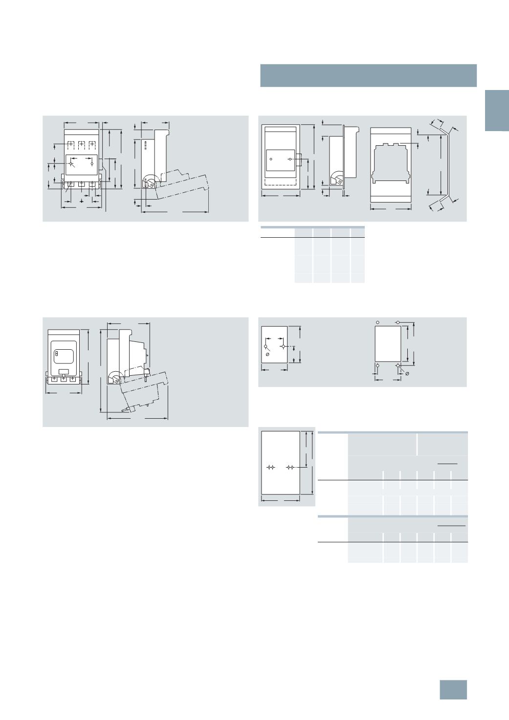
NP LV HRC fuse switch disconnectors
3/87
Siemens ET B1 · 10/2008
3
*
You can order this quantity or a multiple thereof.
1)
h = distance from upper edge of switchboard cutout to center of
disconnector mounting.
2)
With standard molded-plastic masking frame behind panel and corre-
sponding switchboard cutout, the standard switching capacity is reduced
to the following AC 23B values: at 400 V
I
e
160
A, at 500 V from
I
e
160
A to
125
A and at 690 V from
I
e
100
A to 50 A.
3
NP50 60, 160 A
For mounting
3
NP50 60, 160 A
With molded-plastic masking frame
For any type of installation
3
NY1 107molded-plasticmasking
frames
3
NP50 60, 160 A
With fuse monitoring by 3RV1 motor starter protectors,
with plug-in connector
For plastic frames
Cutout
For 3NP50 60, with and
without auxiliary switches
Cutout
For 3NY1 208 mounting kit
For metal frames
Cutouts for 3NP5
173
97
196
63
63
84
34
165
31
NSE0_00226a
Ø
5,8
M8 22
36 36
134
19
228
15
116
97,5
70
Auxiliary switches
c
b
d
12
NSE0_00231a
a
45 2
230
36
NSE0_00227b
135
30
°
30
30
°
30
Type
a b c d
3
NY1 105
135 215 95.5 38
3
NY1 115
135 215 95.5 38
3
NY1 106
135 290 144.5 64
3
NY1 108
135 290 144.5 64
3
NY1 208
149 250 115 53.5
196
300
NSE0_00228b
134
228
161,5
91
205
NSE0_00229a
130
5,8
70
NSE0_00230a
126,5
191
207,5
6
143
NSE0_00906b
B
h
H
Type
Masking frame
between
assembly kit
Min. panel
cutout
Molded-plastic masking frame behind
panel
Type
B H B H h
1)
3
NP50 6
3
NY1 105
2)
135 215 130 206 115
3
NP50 6
3
NY1 125
3
NP52 6
3
NY1 210 222 300 210 293 146
3
NP53 6
3
NY1 211 245 300 235 293 146
3
NP54 6
3
NY1 212 290 300 280 293 146
Molded-plastic masking frame in front of
panel
Type
B H B H h
1)
3
NP50 6
3
NY1 105 135 215 130 205 115
3
NP50 6
3
NY1 208 149 250 143 191 --
3
NP52 6
3
NY1 210 220 300 210 262 132
© Siemens AG 2008