


 233 / 582

BETA Protecting
Low-Voltage Fuse Systems
3
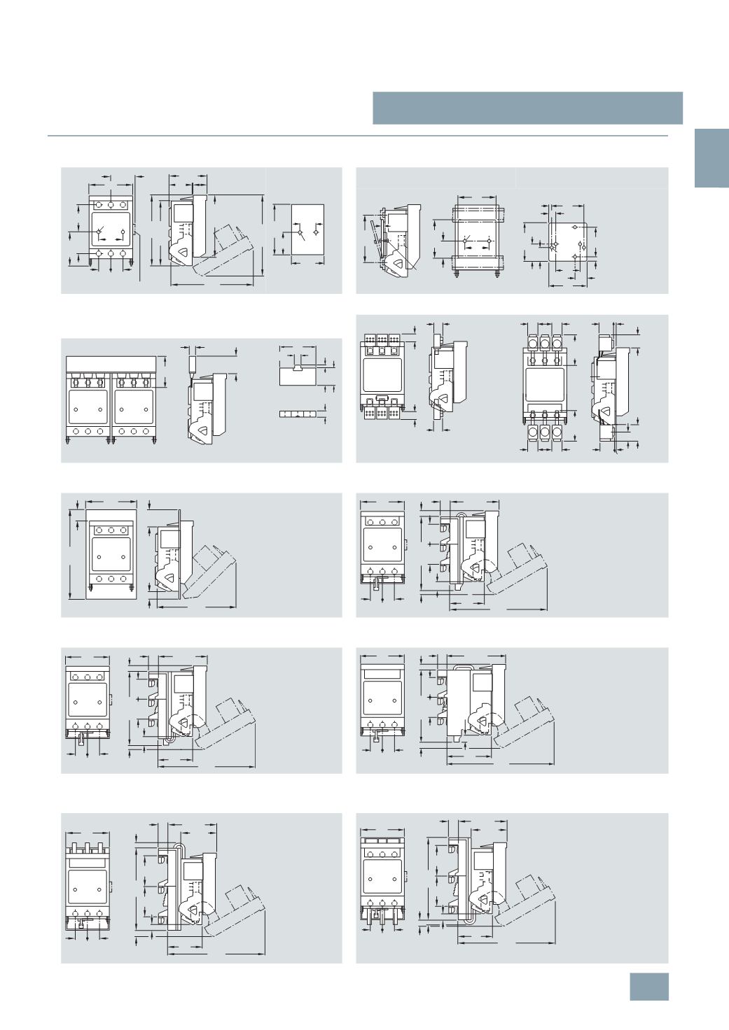
NP LV HRC fuse switch disconnectors
3/83
Siemens ET B1 · 10/2008
3
*
You can order this quantity or a multiple thereof.
■
Dimensional drawings
3
NP40 10
3
NP40 10
3
NY1 995 quick retaining plate
Cutout for 3NP35
and 3NP40 10
With 3NY1 995 quick retaining plate, mount-
ing rail center-to-center clearance: 125 mm
For 3NP40 10 and 3NP40 70
3
NP40 10
With three-phase
3
NY1 237
busbars
For 2 fuse switch disconnectors
3
NY1 265 caps
For three-phase
3
NY1 238
busbars
3
NP40 10
With
3
NY1 235
triple terminals
3
NP40 10
With
3
NY1 236
feeder terminals
3
NP40 10
With
3
NY1 251
molded-plastic masking frames
3
NP40 15-1CJ01
With busbar adapter, flat, busbar width 12 mm or 15 mm
and thickness 5 mm or 10 mm, with bottom connection
3
NP40 15-1CK01
With busbar adapter, flat, busbar width 12 mm or 15 mm and thickness
5
mm or 10 mm, with top connection
3
NP40 15-0CJ01
With busbar adapter, deep, busbar width 12 mm or 15 mm
and thickness 5 mm or 10 mm, with bottom connection
3
NP40 16-1CJ01
With busbar adapter, rails of width 12, 15, 20 mm or 30 mm and thickness
5
mm or 10 mm, flat, T, I profiles and other renowned busbar systems,
with bottom connection
3
NP40 16-1CK01
With busbar adapter, rails of width 12, 15, 20, 25 mm or 30 mm and thickness
5
mm or 10 mm, flat, T, I profiles and other renowned busbar systems,
with top connection
73,5
44
127,5
64,5
44,5
25,5 25,5
NSE0_00190b
48
44
52
Ø5,8
50
143
126,5
174
27
168,5
Auxiliary switch
85
125
NSE0 00192a
50
97,5
43,5
2,5
M5
Ø5,8
70
NSE0_00193a
97,5
43,5
85
70 13,8
7,5
17,5
28,5
34,5
50
M5
For installation
in STAB 8GD
wall-mounted
distribution
boards, upper
perforations
with 50 mm
clearance are
required.
M 5
50
100
155
68
NSE0_00191a
NSE 00196b
9,5
18
16
18
NSE 00197b
62,5
21
21
28 3,5
28,5
62,5
21
21
28
3,5
35
20
NSE0_00194b
63
28,5
14
72
10,5
5
13
35
12
NSE0_00195a
130
NSE0_ 00200b
41,5
215
58,5
30
174
89
100,5
NSE 00201b
25,5 25,5
201
19
16,5
40 40
144,5
7,5
18
72
89
100,5
NSE 00202b
25,5 25,5
72
19
16,5
40 40
144,5
7,5
18
201
89
NSE 00907b
25,5 25,5
16,5
40
144,5
40
7,5
19 121,5
18
93
222
89
NSE 00204b
25,5 25,5
10,5
60
60
168
11,5
14
69,5
19 100,5
201
72
89
NSE 00205b
25,5 25,5
10
60
60
168
11,5
72
14
69,5
19 100,5
201
© Siemens AG 2008