


 211 / 582

BETA Protecting
Low-Voltage Fuse Systems
3
NH LV HRC fuse bases
3/61
Siemens ET B1 · 10/2008
3
*
You can order this quantity or a multiple thereof.
■
More information
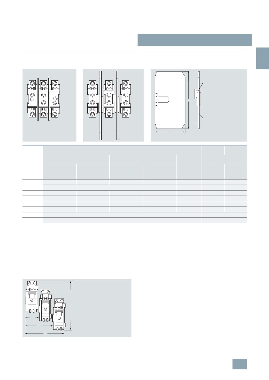
Space requirements when installing LV HRC fuse bases
1)
This measurement specifies the required overall mounting depth with base
d and the overall mounting height h.
2)
Placing an additional base on the barrier and plug-on part does not
increase the distance, rather the bases lie flat directly on top of one
another.
3)
If the bases are installed directly on a side wall in the distribution board,
one spacer part can be broken off. This would reduce the distance
measurement.
1
LV HRC fuse base, 3P
3
LV HRC fuse bases, 1P
LV HRC partition
Size
Mounting width (mm) of LV HRC fuse bases
Mounting
height (mm)
Mounting
depth (mm)
1
unit, 3P
3
units, 1P
Distance
through spacer
3
NX2 0.. barriers with
matching bases
1)
Bases with phase
barrier, without end
barrier
Bases with phase
barrier and 2 end
barriers
Bases with phase
barrier, without end
barrier
Bases with phase
barrier and 2 end
barriers
h
d
000/00
102
106
100
104
2)
2
138
86
LV HRC bus-mounting bases see page 3/58
–
114
90
0
--
--
128
142
7
178
90
1
163
177
158
172
7
202
110
2
--
--
184
224
20
3)
227
118
3
--
--
208
272
32
3)
242
132
4
Installation without barriers; for mounting see page 3/58
n/a
4
a
Can only be used in bases with swivel mechanism
n/a
I2_11361
I2_11362
h
t
Spacer
Barrier
I2_11363a
Space requirements when installing LV HRC bus-mounting
bases
Space requirements for 3-piece, 1-pole 3NH3 036 and 3NH3 037 LV HRC
bus-mounting bases, staggered
82
I2_11364
71
38
Saddle-type terminal connection: 175
Terminal strip: 182
© Siemens AG 2008