


 209 / 582

BETA Protecting
Low-Voltage Fuse Systems
3
NH LV HRC fuse bases
3/59
Siemens ET B1 · 10/2008
3
*
You can order this quantity or a multiple thereof.
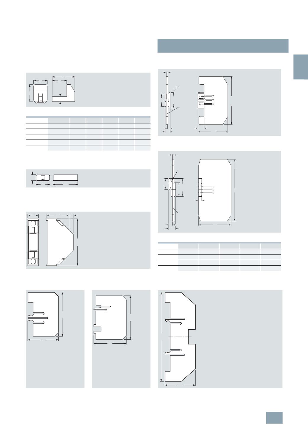
LV HRC contact covers for LV HRC fuse bases and
LV HRC bus-mounting bases
1)
Size 000/00 to 3
3
NX3 105 to 3NX3 108, 3NX3 114
Sizes
Type
a
b
c
d
e
000/00
3
NX3 105
1)
38
47.5 34
11.5 30
0
3
NX3 114 51.5 47.5 34
11.5 30
1
3
NX3 106 61.5 57
42.5 35
46
2
3
NX3 107 74
65
51
35
46
3
3
NX3 108 81.5 77.5 57.5 35
46
1)
The 3NX3 105 LV HRC contact covers can be used for both LV HRC fuse
bases and LV HRC bus-mounting bases.
LV HRC contact covers for LV HRC bus-mounting bases
3
NX3 113 for the incoming terminal, dimensional drawing 3NX3 105, for the
outgoing terminal, see dimensional drawing above
3
NX3 115 LV HRC protective covers, with 3NX3 116 LV HRC covers
Size 000/00, degree of protection IP2X
I2_11365a
c
b
d
e
a
50
30
I2_11368
11,5
LV HRC partitions for LV HRC fuse bases
Size 000/00
3
NX3 023
Sizes 0 to 3
3
NX2 030, 3NX2 024 to 3NX2 026
Sizes
Type
a
b
c
d
0
3
NX2 030 87.6
178.5
7.7
12.3
1
3
NX2 024 107.3
202.5
7.7
12.3
2
3
NX2 025 115.3
227.5
14.2
25.1
3
3
NX2 026 129.8
242
20.2
37.2
138,5
86
6,2
1,65
3,5
16,1
36,5
31
Spacer
Partition
I2_06492a
b
a
14,3
c
1,6
d
41,3
55,8
35
Spacer
Partition
I2_06493a
LV HRC partitions for LV HRC bus-mounting bases
Size 000/00
Phase barrier
End barrier
For LV HRC bus-mounting bases in tandem design
3
NX2 027
3
NX2 028
3
NX2 031
114
82
I2_06499a
114
87
I2_06502b
230
81,5
I2_06684a
© Siemens AG 2008