




 371 / 543

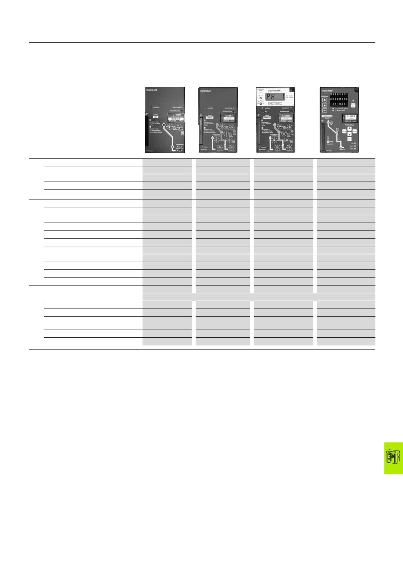
IZM circuit-breakers, IN switch-disconnectors
Electronic releases for IZM26 circuit-breakers
2010 CA08103002Z-EN
www.eaton.com18/41
IZM26 ...-A...
System protection
DTA
Digitrip 520 LI
IZM26 ...-V...
Selectivity protection
DTV
Digitrip 520 LSI(G)
IZM26 ...-U...
Universal protection
DTU
Digitrip 520MC LSI(G)
IZM26 ...-P...
Universal protection with
power measuring
DTP
Digitrip 1150i LSI(G)
System diagnostics
Cause of trip LEDs
●
●
●
●
Current at trip point
–
–
●
1)
●
1)
Remote signaling contacts
A
–
–
●
1)
●
1)
Programmable signal contacts
A
–
–
–
●
1)
System monitor
Digital display
–
–
4-digit LED
24-digit LED
Current display (%)
–
–
●
●
Phase voltage (%)
–
–
–
●
Power and energy (%)
–
–
–
●
Apparent power kVA reference and delivery –
–
–
●
Reactive power kVAR
–
–
–
●
Power factor
–
–
–
●
Crest factor
–
–
–
●
Power quality, harmonics
–
–
–
●
THD factor (%)
–
–
–
●
Fieldbus communication
–
–
Modbus, PROFIBUS
Modbus, PROFIBUS
Additional functions
Trip history (3 events)
–
–
–
●
Electronic operations counter
–
–
–
●
Test possibility
2)
Hand held test unit
Hand held test unit
Hand held test unit
Hand held test unit and
integrated function
Maintenance mode ARMS
–
–
○
1)
○
1)
Curve-form plotting
–
–
–
●
Notes
l
n
= rating plug (rate current module) = rated operational current current
transformer
l
r
= Set value overload trip (= rated operational current of system)
1)
Requires an external 24 V DC control voltage supply.
2)
Hand-held tester for simulating secondary current
● Standard
○ Optional
IZM26...