


 376 / 543

2010 CA08103002Z-EN
www.eaton.com18/46 IZM circuit-breakers, IN switch-disconnectors
IZM26 air circuit-breakers, Components for communication
IZM26aircircuit-breakers,Components forcommunication
Components for IZM26 communication
The IZM26 series devices can be connected to a PROFIBUS-DP or Modbus RTU
filed bus. Interfaces IZM-PMINT and IZM-MMINT are compact devices for mount-
ing on top-hat rails, i.e. independently of the switch. They output all information
available in the trip unit to the fieldbus, including switch status, current, voltage,
power, and energy, as well as diagnostic information such as overcurrent, phase
asymmetry and overvoltage. The fieldbus also facilitates actuation of the motor
operator and therefore its remote operation.
Requirements
The communications modules can be used in combination with IZMX26…-U
or IZMX26…-P… circuit-breakers.
PROFIBUS-DP configuration
Communications module IZM-PMINT has a 9-pin D-Sub socket for connection to
PROFIBUS. The module works as a slave on PROFIBUS-DP; the data is defined
through a standardized device master data file, which permits smooth integration
of the IZM in a DP line.
PROFIBUS
• On the PROFIBUS-DP side the module supports automatic baud rate detection;
the PROFIBUS-DP bus address is set through the trip unit’s display. The maximum
cable length is 2.4 km.
• To operate the IZM-PMINT, a supply voltage of 24 V DC or 240 V AC is required.
INCOM
• The data connection to the circuit-breaker is implemented through a serial
INCOM data connection. A shielded, twisted-pair data cable (recommended are
Belden 9463 or 3073F) can be used.
• The INCOM bus must be terminated with a 100 Ω terminating resistor, connected
between the two cable strands at the circuit-breaker end.
• The maximum cable length is 3 km.
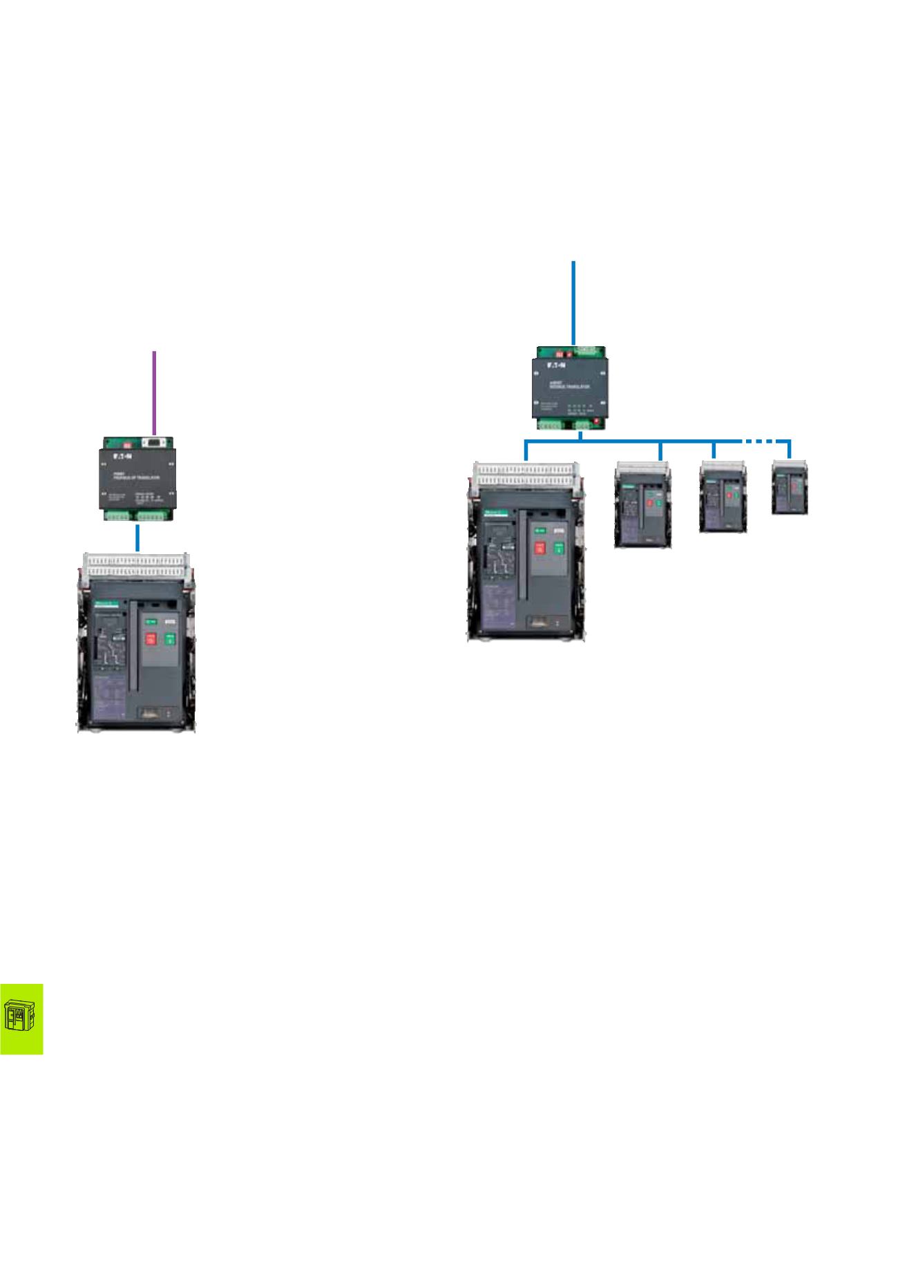
with U or P release
PROFIBUS-DP
IZM-PMINT
INCOM
IZM26
Data access via PROFIBUS-DP
The data on PROFIBUS-DP are offered according to the profile for low-voltage
switchgear (LVSG) of PROFIBUS International (PROFIBUS and PROFINET User
Group). Five different data structures with varying numbers of parameters are
available through the device master data file. This allows a data filter to be easily
implemented, which simplifies integration of the IZM data into the control
system.
Modbus configuration
Communications module IZM-MMINT has a plug-in screw terminal for connection
to Modbus. The module operates as a Modbus slave. The interface to the circuit-
breaker can be operated as a bus, so that up to 32 IZM26 units can be connected to
an IZM-MMINT. This makes the use of the IZM with the Modbus architecture
specially efficient.
Modbus
• The baud rate for Modbus communications is selectable with coding switches on
the IZM-MMINT; the bus address (up to 247) is set through the display of the trip
unit. The maximum cable length is 1.2 km.
• The Modbus must be terminated with a 120 Ω terminating resistor. If the
IZM-MMINT is the last device in the network, a built-in terminating resistor
can be activated there with a coding switch.
• To operate the IZM-MMINT, a supply voltage of 24 V DC or 240 V AC is required.
INCOM
• The data connection to the circuit-breaker is implemented through a serial
INCOM bus connection. A shielded, twisted-pair data cable (recommended
are Belden 9463 or 3073F) can be used.
• The INCOM bus must be terminated with a 100 Ω terminating resistor, connected
between the two cable strands at the circuit-breaker end.
• The maximum cable length is 3 km.
Data access via Modbus
The data for each circuit-breaker connected to the INCOM bus is contained in
comprehensive data tables. Each data point is available as floating-point (IEEE) or
fixed--point value. This variance allows the integration of the IZM to be adapted to
the Modbus architecture. This allows a data filter to be easily implemented, which
simplifies integration of the IZM data into the control system.
Modbus
IZM-MMINT
INCOM
IZM26
1
2
3
32
with U or P release