


 15 / 253

Electronic relays
Timing relays
2010
CA08103002Z-EN
www.eaton.comDILET, ETR4
11/11
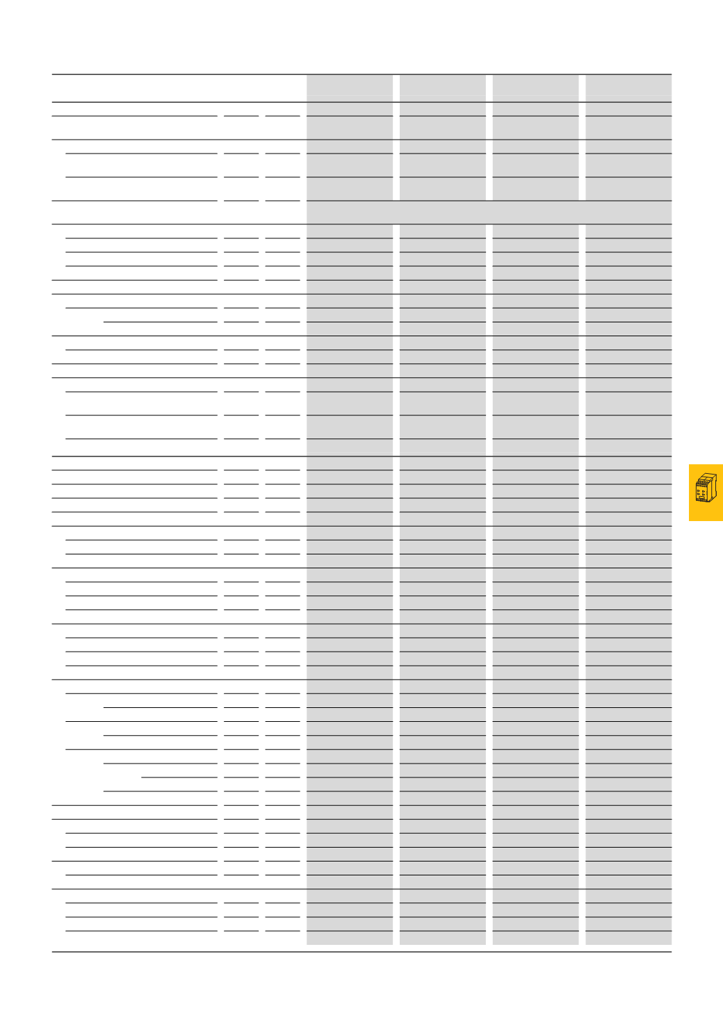
DILET,ETR4Timing relays
DILET-A
DILET-W
ETR4-A
ETR4-W
General
Standards
IEC/EN 61812
VDE 0435
IEC/EN 61812
VDE 0435
IEC/EN 61812
VDE 0435
IEC/EN 61812
VDE 0435
Lifespan, mechanical
AC operated
Switch
operations
x 10
6
30
30
30
30
DC operated
Switch
operations
x 10
6
30
30
30
30
Climatic proofing
Damp heat, constant, to IEC 60068-2-78;
Damp heat, cyclic, to IEC 60068-2-30
Ambient temperature
Storage
°C
-45 - 60
-45 - 60
Open
°C
-20 - 60
-20 - 60
-25 - 60
-25 - 60
Encapsulated
°C
-20 - 45
-20 - 45
-25 - 45
-25 - 45
Mounting position
Any
Any
Any
Any
Mechanical shock resistance (IEC/EN 60068-2-27)
Half-sinusoidal shock 20 ms
N/O
g
4
4
4
4
Degree of protection
Clamps
IP20
IP20
IP20
IP20
Weight
kg
0.09
0.09
0.1
0.1
Terminal capacity
Solid
mm
2
1
x (0.75 - 2.5)
2
x (0.75 - 2.5)
1
x (0.75 - 2.5)
2
x (0.75 - 2.5)
1
x (0.75 - 2.5)
2
x (0.75 - 1.5)
1
x (0.75 - 2.5)
2
x (0.75 - 1.5)
Flexible with ferrule
mm
2
1
x (0.75 - 1.5)
2
x (0.75 - 1.5)
1
x (0.75 - 1.5)
2
x (0.75 - 1.5)
1
x (0.75 - 2.5)
2
x (0.75 - 1.5)
1
x (0.75 - 2.5)
2
x (0.75 - 1.5)
Solid or stranded
AWG 1 x (18 - 14)
1
x (18 - 14)
1
x (20 - 14)
1
x (20 - 14)
Contacts
Rated impulse withstand voltage
U
imp
V AC 6000
6000
6000
6000
Overvoltage category/pollution degree
III/2
III/2
III/2
III/2
Rated insulation voltage
U
i
V AC 600
600
600
600
Rated operating voltage
U
e
V AC 440
440
440
440
Safe isolation according to EN 61140
Between coil and auxiliary contacts
V AC 250
250
250
250
Between the auxiliary contacts
V AC 250
250
250
250
Making capacity
AC-14 p.f. ϕ = 0.3 440 V
A
48
48
48
48
AC-15 p.f. ϕ = 0.3 220 V
A
50
50
50
50
DC-11 L/R ≦ 40 ms
x I
e
1.1
1.1
1.1
1.1
Breaking capacity
AC-14 p.f. ϕ = 0.3 440 V
A
3
3
3
3
AC-15 p.f. ϕ = 0.3 220 V
A
3
3
3
3
DC-11 L/R ≦ 40 ms
x I
e
1.1
1.1
1.1
1.1
Rated operation current
AC-14
440
V
I
e
A
3
3
3
3
AC-15
220
V (230 V)
I
e
A
3
3
3
3
DC-11
1)
L/R max. 15 ms
24
V
I
e
A
1.5
1.5
1.5
1.5
L/R max. 50 ms
A
1.2
1.2
1.2
1.2
Conventional thermal current
I
th
A
6
6
6
6
General use
AC operated
V
250
250
250
250
AC operated
A
6
6
6
6
Pilot duty
AC operated
B300
B300
B300
B300
Short-circuit rating without welding
2)
Max. fuse, N/O (normally open)
A gG/gL 6
6
6
6
Max. fuse, N/C (normally closed)
A gG/gL 6
6
6
6
Max. overcurrent protective device, 220/230 V
Part no.
–
–
FAZ-B4/1-HI
FAZ-B4/1-HI
Notes
1)
Making and breaking conditions to DC13, time constant as stated
2)
When supplied directly from mains or transformer > 1000 VA