


 364 / 439

9/32
DS7 soft starters
Soft starters
2010
CA08103002Z-EN
www.eaton.comSoft starters
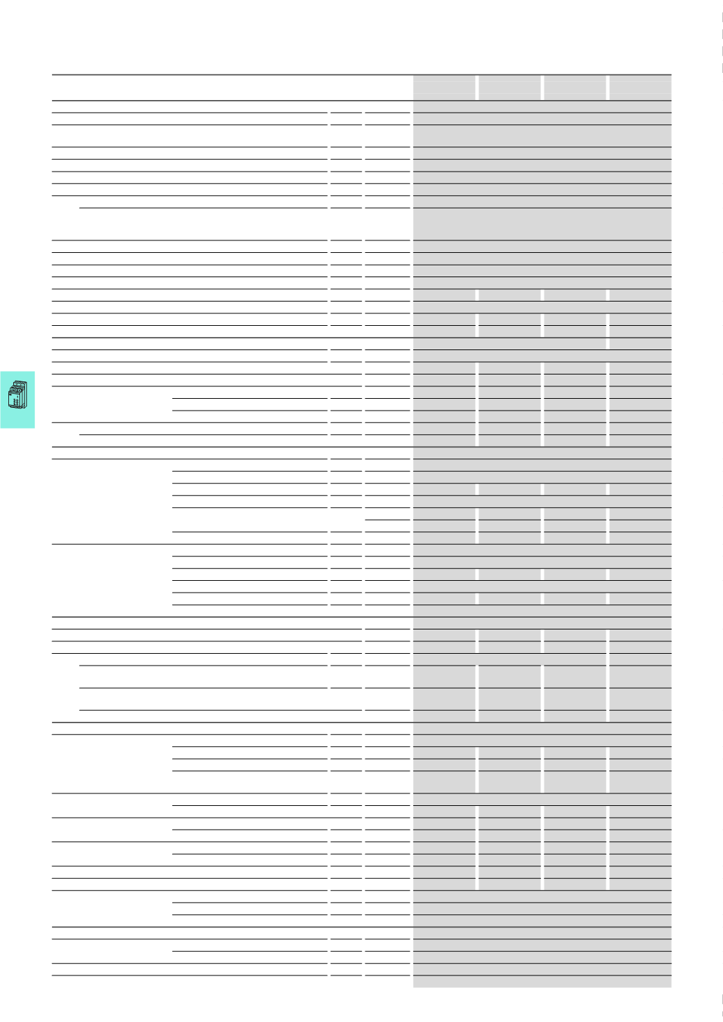
DS7-340SX004 DS7-340SX007 DS7-340SX009 DS7-340SX012
General
Standards
IEC/EN 60 947-4-2
Climatic proofing
Damp heat, cyclic, to DIN IEC Part 68 2-10,
Damp heat, constant, to DIN IEC 68 Part 2-3
Ambient temperature
°C
0…40,
up to 60 °C at 1 % derating per Kelvin temperature rise
Ambient temperature storage
°C
-25 -
+55
Installation altitude
Higher installation altitude upon request
0…1000
m, above that 1 % derating per 100 m, up to 2000 m
Mounting position
Vertical
Protection type
IP20
Protection type applies to the front and operator control and
operating elements.
Protection type from all sides is IP00.
Protection type IP40 can be achieved on all sides with covers from the
NZM range.
Protection against direct contact
Finger- and back-of-hand proof
Overvoltage category/pollution degree
II/2
Mechanical shock resistance
8
g/11 ms
Vibration resistance to EN 60721-3-2
2
M2
Average heat dissipation with nominal load cycle
W 0.2
0.35
0.45
0.6
Dimensions (W x H x D)
mm
45
x 130 x 95
Radio interference level
B
Weight
kg
0.35
0.35
0.35
0.35
Main contacts
Rated operational voltage
V AC
230 - 460
Mains frequency
Hz
50/60
Rated operational current
AC-53 (motor loads)
I
e
A
4
7
9
12
Assigned motor rating
230
V
P
kWh
0.75
1.5
2.2
3
400
V
P
kWh
1.5
3
4
5.5
480
V
P
HP
2
3
5
7.5
Overload cycle to EN 60947-4-2
AC-53a (int. bypass)
For AC-53a:3-5:75-10
A
4
7
9
12
Terminal capacity
Power cable
(
box terminal)
Solid
mm
2
1
x (0.75 - 4); 2 x (0.75 - 2.5)
Flexible with ferrule
mm
2
1
x (0.75 - 2.5); 2 x (0.75 - 2.5)
Stranded
mm
2
–
–
–
–
Solid or stranded
AWG
18 - 10
Flat conductor
min, mm –
–
–
–
max, mm –
–
–
–
Tightening torque
Nm
1.2
1.2
1.2
1.2
Control cables
Solid
mm
2
1
x (0.75 - 4); 2 x (0.75 - 2.5)
Flexible with ferrule
mm
2
1
x (0.75 - 2.5); 2 x (0.75 - 2.5)
Stranded
mm
2
–
–
–
–
Solid or stranded
AWG
18 - 10
Tightening torque
Nm
1.2
1.2
1.2
1.2
Screwdriver (flat blade)
mm
0.8
x 5.5; 1 x 6
Power section
Rated impulse withstand voltage
U
imp
1.2/50
μs kV
4
4
4
4
Rated insulation voltage
U
i
V
500
500
500
500
Short-circuit rating
Type "1" coordination For AC-53a:3-5:75-10
PKZM0-4
(
+ CL-PKZ0)
PKZM0-10
(
+ CL-PKZ0)
PKZM0-10
(
+ CL-PKZ0)
PKZM0-12
(
+ CL-PKZ0)
Type "2" coordination
(
in addition to fuses for type "1" of coordination)
3
x 50.179.06-16 3 x 50.140.06-25 3 x 20.282.20-32 3 x 20.282.20-32
Fuse holders
3
x 51.060.04
3
x 51.060.04
3
x 51.060.04
3
x 51.060.04
Control circuit
Controller supply voltage
Voltage
U
s
V
24
V AC/DC + 10 % / - 15 %
Current consumption at no load 24 V DC
mA
–
–
–
–
Current consumption in operation at 24 V DC
mA
–
–
–
–
Current consumption at peak load
(
close bypass) at 24 V DC
mA/ms
–
–
–
–
Control voltage range
AC operated
24
V AC/DC + 10 % / - 15 %
Current consumption at 230 V DC
mA
–
–
–
–
Pick-up voltage
DC operated
V DC
+17.3 - +27
+17.3 - +27
+17.3 - +27
+17.3 - +27
AC operated
V AC
–
–
–
–
Drop-out voltage
DC operated
V DC
0 -
+3
0 -
+3
0 -
+3
0 -
+3
AC operated
V AC
–
–
–
–
Pick-up time
AC operated
ms
–
–
–
–
Drop-out time
AC operated
ms
–
–
–
–
Relay outputs
Number
1 (
TOR)
Voltage range
V AC
250
Current range
A
1
A, AC-1
Soft start functions
Ramp times
Acceleration
s
1 - 30
Deceleration
s
0 - 30
Start voltage (= switch-off voltage)
30 % - 100 %
Voltage reduction at stop
8 %
DS7-340SX