


 234 / 336

Cam switches, switch-disconnectors
2010 CA08103002Z-EN
www.eaton.com4/9
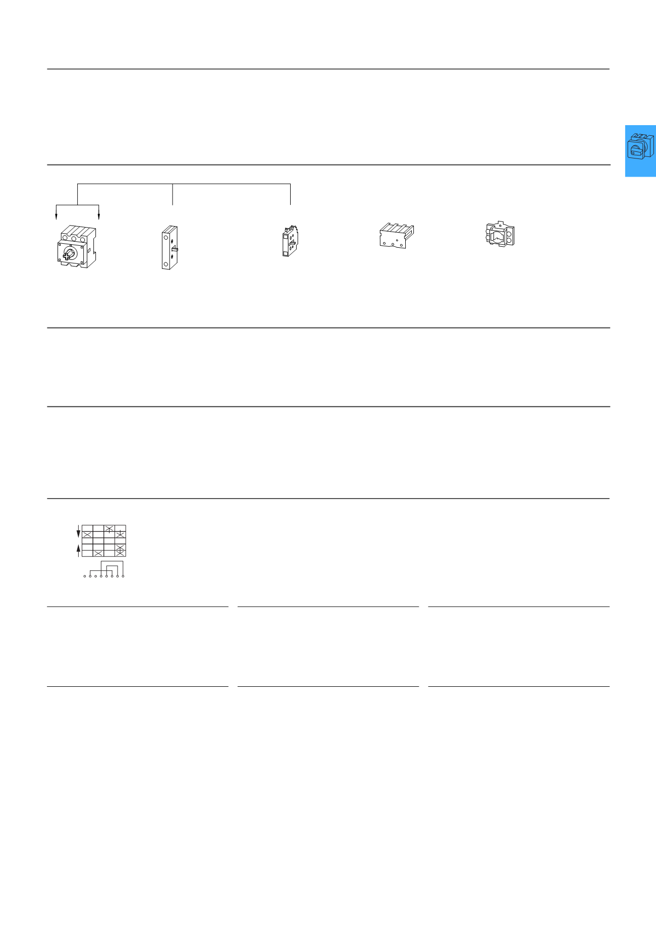
Switch-disconnectors P1 and P3
Key to part numbers
P. . . . . . . . . . . . - . . . . . . . . . . . . . . . . . . . . . . . . . . . . / . . . . . . . . . . . . . . . . . . . . - . . . . . . . . . . . . . . . . . . / . . . . . . . . . . . . . . . . . . . . .
Switch size
P1 or P3
Rated uninterrupted current
Mounting form
→Page 4/2
Part no. suffix
(if required)
Accessories
from→Page 7/47
Add-on functions due to modular system
TM mini cam switches
The TMmini cam switch is a particularly small switch
with a small space requirement. It is ideally suited for
small voltages and currents such as electronic
controls. For greater safety the contacts are gold
plated.
TM switches have consecutive terminal markings
starting with 1.
Selection pages: Starting on→Page7/54
Key to part numbers
TM-. . . . . . . . . . . . . . . . . . . . . . . . . - . . . . . . . . . . . . . . . . . . . . . . . / . . . . . . . . . . . . . . . . . . . . + . . . . . . . . . . . . . . . . . .
Number of contact chambers
= contact units
Contact sequence
number
Mounting form
→Page 4/2
Accessories
→Page 7/59
Circuit representation
(see also ordering example in the electronic
catalogue)
Switch from 0 to 1
Contact 1 – 2 open,
Contact 3 – 4 open,
Contact 5 – 6 open,
Contact 7 – 8 closed
Switch from 1 to START
with automatic return to 1
Contact 1 – 2 open,
Contact 3 – 4 closed,
Contact 5 – 6 open,
Contact 7 – 8 remains closed
Switch from 1 to 0
Contact 1 – 2 open,
Contact 3 – 4 open,
Contact 5 – 6 open,
Contact 7 – 8 open
Switch from 0 to 2
Contact 1 – 2 closed,
Contact 3 – 4 open,
Contact 5 – 6 open,
Contact 7 – 8 closed
Switch from 2 to START
with automatic return to 2
Contact 1 – 2 open,
Contact 3 – 4 open,
Contact 5 – 6 closes with early make,
Contact 7 – 8 opens with late break
Switch from 2 to 0
Contact 1 – 2 open,
Contact 3 – 4 open,
Contact 5 – 6 open,
Contact 7 – 8 open
H-P...
UV-P...
N-P...Z
HI 11-P1/P3Z
N-P...E
HI 11-P1/P3E
3-pole basic unit
.../E or .../Z
Switched neutral
Can be fitted left
or right
(for P1.../I: left only)
Auxiliary contact
Can be fitted left
or right
(for P1.../I: left only)
Terminal shroud
can be fitted at
top or bottom
N + PE terminals,
also as cover interlock
on .../Z-switches.
or
or
1
2
3
4
5
6
7
8
START
1
0
2
START
Links
Terminal markings
Front plate labeling
P1, P3, TM