


 203 / 336

3/90 Sensors
Comet series
2010 CA08103002Z-EN
www.eaton.comOptical sensors
Optical sensorsCometseries
Engineering
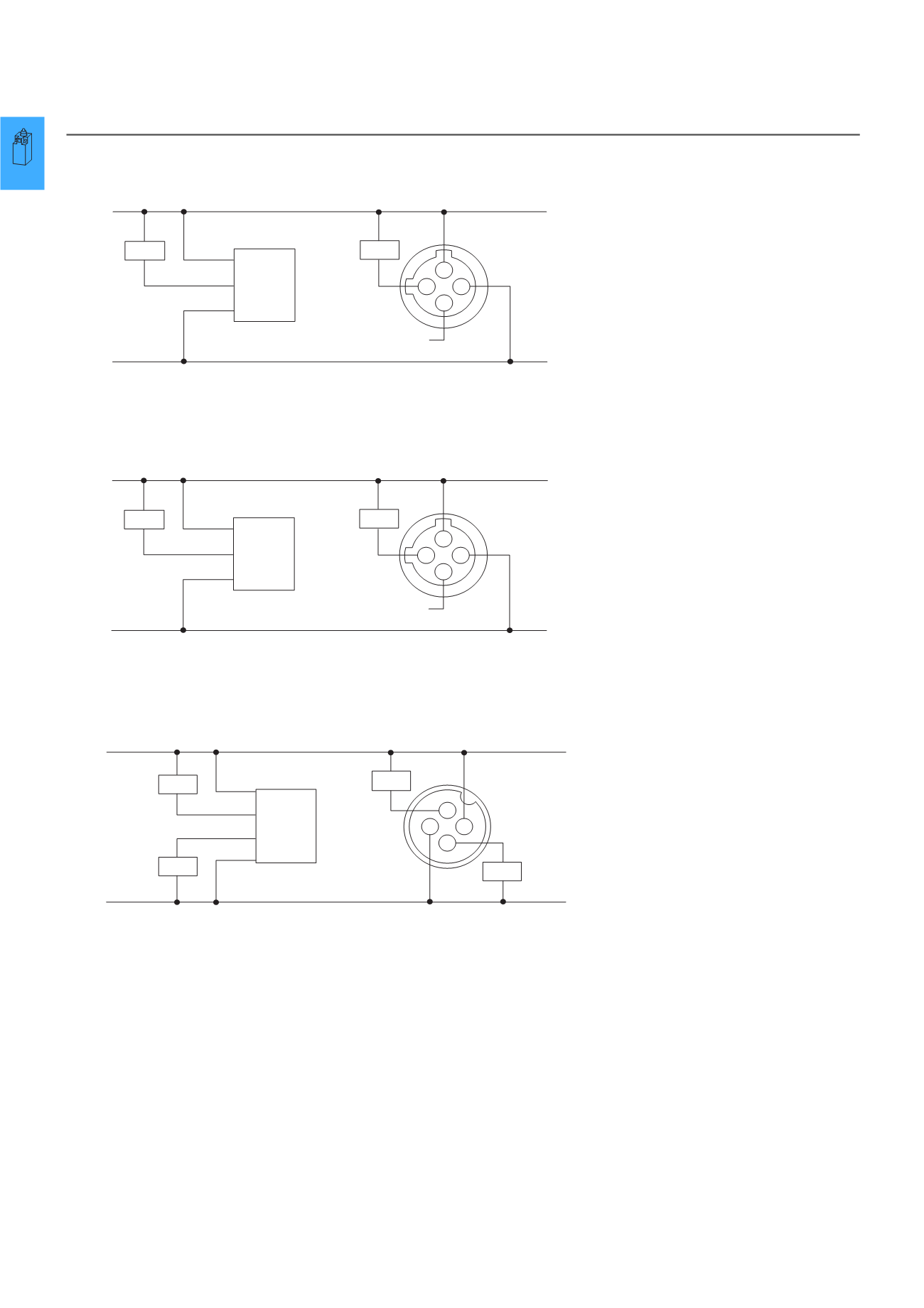
Circuit diagram
AC/DC connection (AC units)
AC/DC connection (DC units)
DC connection (DC units)
Note:
AC/DC sensors have AC plug connectors. Take into account when using with DC voltage.
L1
L2
L1
L2
Load
4
1
2
3
Load
AC/DC
Comet
Switched
L1
Switched
L1
20 to 264 V AC
Blue
Brown
Black
1)
M12 plug connector
(Red/White)
(Red/Black)
(Red)
1)
No Connection (Green)
Connection cable
1) Note: Cable not connected on source of thru-beam sensors.
(-)
+V
Load
4
1
2
3
Load
(-)
+V
AC/DC
Comet
NPN
Output
(Sink)
NPN
Output
(Sink)
Blue
Brown
Black
1)
M12 Plug connector
(Red/White)
(Red/Black)
(Red)
1)
No Connection (Green)
Connection cable
15 to 30 V DC
1) Note: Cable not connected on source of thru-beam sensors.
(-)
+V
Load
(-)
+V
4
1 3
2
Load
Load
Load
DC
Comet
NPN
Output
(Sink)
NPN
Output
(Sink)
PNP
Output
(Source)
PNP
Output
(Source)
Red
Black
Green 1)
(Brown)
White 1)
White 1)
(Blue)
(Black) 1)
10 to 30 V DC
M12 plug connector
Connection cable
1) Note: Cable not connected on source of thru-beam sensors.