


 66 / 78

TECHNI CAL DATA
MCCB
66
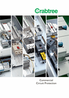
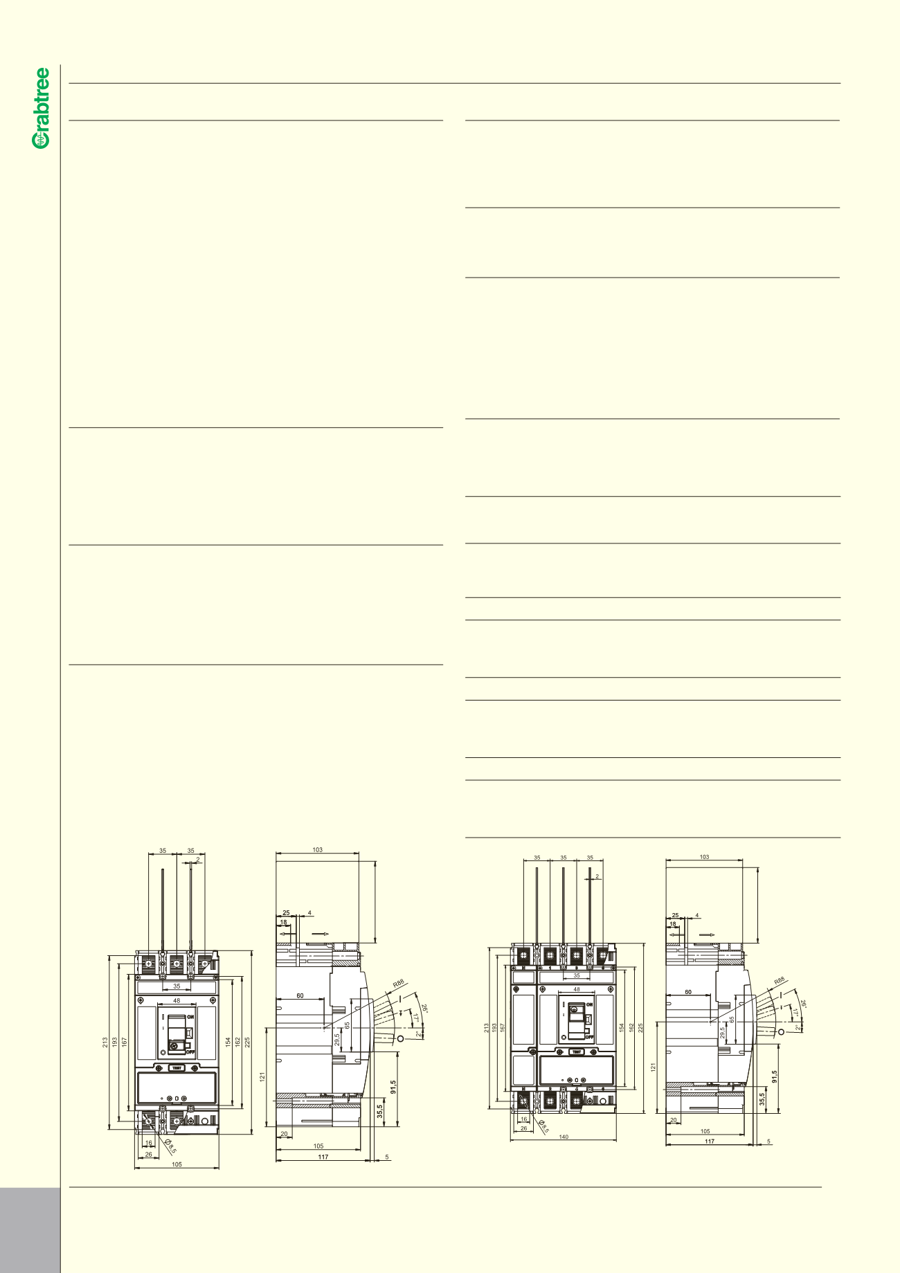
7T2 FRAME MCCBs TECHNICAL SPECIFICATION
l
7T2 FRAME SPECIFICATION
I
• Specification IEC 60947-2 & IEC 60947-3
• Current Range 40 – 250A
• Ue Rated Operation Voltage 690V AC
• Ui Rated Insulation Voltage 690V AC
• Rated Frequency 50/60Hz
• Release Electronic
• Thermal Adjustment 0.4 – 1.0 x Trip Unit
Rated Current
• Instantaneous Adjustment Adjustable
• Icu (415V) Short Circuit Breaking Capacity 7T2S 36kA 7T2H 65kA
• Ambient Range -40°C to 55°C
• Working Environment Both Dry and Tropical
Climates
• Mechanical Endurance 30,000 Cycles
7T2 FRAME FEATURES
I
The 7T2 circuit breaker consists of a switching unit and either a range of
different rated electronic trip units or a switch disconnector module. The
modular design provides the maximum flexibilty as the user can decide not
only the rating but also the function, disconnector or protective device. With
a wide setting bandwidth electronic trip units offer unparalled functionality.
AVAILABLE OPTIONS
I
• ST UVR
• Aux SW
• Rotary Handle (available on request)
• Padlocking
• Terminal Shrouds
SHORT CIRCUIT BREAKING CAPACITY
I
Ue 7T2S Icu 7T2H Icu
280 V 60 kA 100kA
415 V 36kA 65kA
Ics
= 50% Icu
TRIP UNIT SETTINGS
I
Over current
I
R = 0.4 - 1.0 x
I
n
Instantaneous 4 or 8 x
I
R
I
n - Nominal Trip Unit Rating
MAIN CONNECTIONS
I
Front-connected clamps –
150mm
2
AUXILIARY EQUIPMENT OPTIONS (RETRO-FITTABLE)
I
a) UVR
b) Shunt Trip
c) Auxiliary Switches
Shunt Trip Voltage Range
≥
70%
Under Voltage Release Threshold
≤
35%
Input Power of Auxiliary Releases < 3VA AC, < 3W DC
CURRENT CHARACTERISTICS
I
Maximum earth fault loop impendance (Zs) for circuit breakers with Uo of
230V, incorporating the 0.95 C
min
factor, 17th Edition IET Wiring Regulations
(BS 7671:2008), Amendment 3 effective from January 1st 2015
IR & II SET AT MINIMUM
CURRENT VALUE (A)
OHMIC VALUE
0.4
5
0.4
5
AMPS SECONDS SECONDS VOLTAGE SECONDS SECONDS
100
150A 150A
230V 1.457
Ω
1.457
Ω
160
240A 240A
230V 0.910
Ω
0.910
Ω
250
375A 375A
230V 0.583
Ω
0.583
Ω
IR SET AT MINIMUM & II SET AT MAXIMUM
100
320A 230A
230V 0.683
Ω
0.950
Ω
160
512A 368A
230V 0.427
Ω
0.594
Ω
250
800A 575A
230V 0.273
Ω
0.380
Ω
IR & II SET AT MAXIMUM
100
800A 600A
230V 0.273
Ω
0.364
Ω
160
1280A 960A
230V 0.171
Ω
0.228
Ω
250
2000A 1500A 230V 0.109
Ω
0.146
Ω
IR SET AT MAXIMUM & II SET AT MINIMUM
100
400A 400A
230V 0.546
Ω
0.546
Ω
160
640A 640A
230V 0.341
Ω
0.341
Ω
250
1000A 1000A 230V 0.219
Ω
0.219
Ω
100 ... 150
100 ... 150