


 2 / 4
2 / 4

NURSECALL800 STANDARDSYSTEMCOMPONENTS
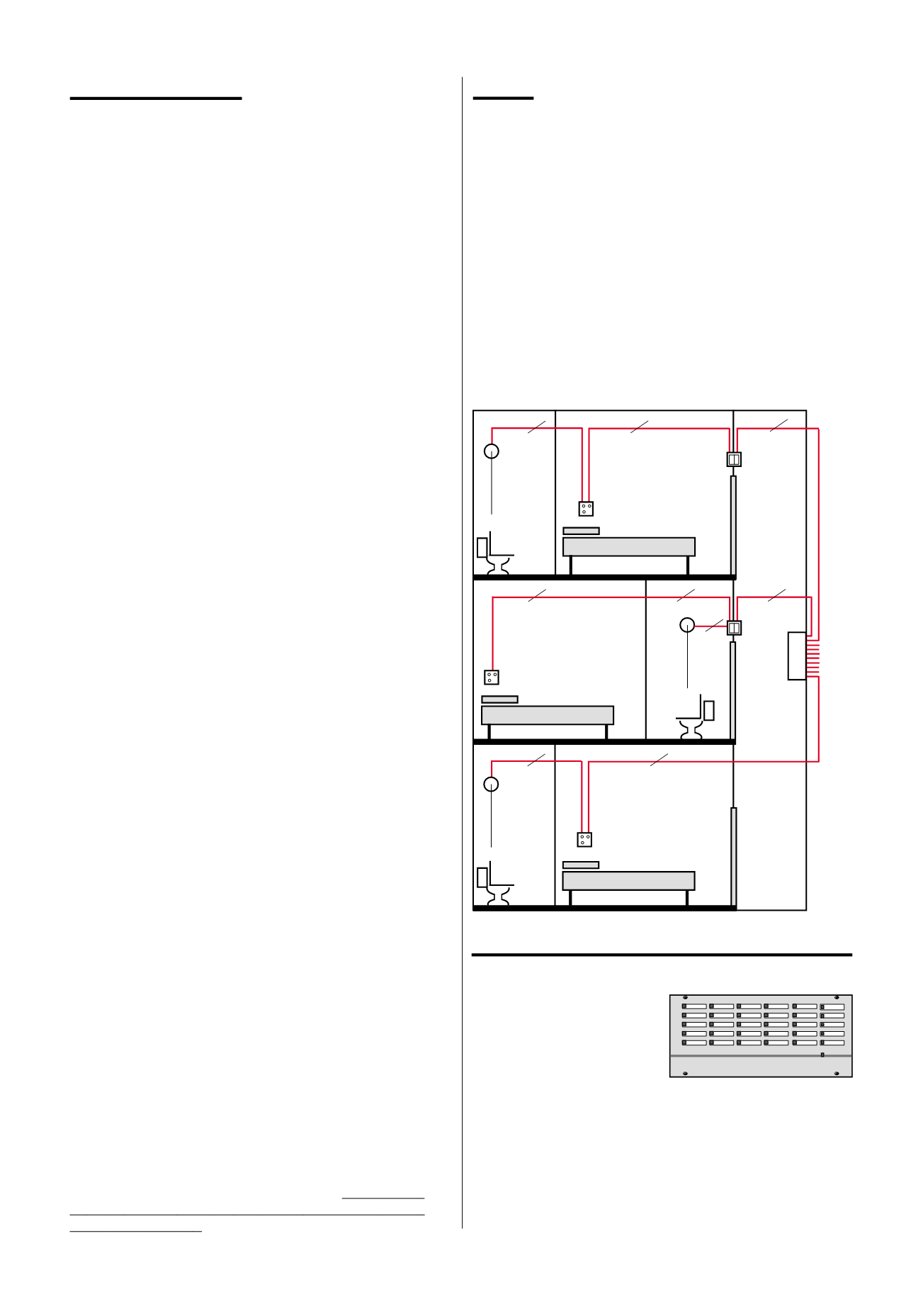
STANDARD INDICATOR PANELS
DESIGNING A SYSTEM
Before installation begins, be sure to check with the relevant
person(s) in case there are any special requirements.
Indicator Panels:
Decide where to site the master panel and,
if required, any repeater panels. Panels must be sited internally
in a clean dry area which is readily accessible by the panels
user(s). The master panel needs a mains supply from a fused
spur. Up to three repeaters can be fitted to a standard
system. Up to ten repeaters can be fitted to an emergency
system as these consume much less current.
Call Points, Reset Points and Overdoor Lights:
Any number of
call points (of any kind), reset points and overdoor lights can
be wired on one zone. Call points should be positioned next to
each bed, in each bathroom and WC, and in lounges, dining
rooms, etc (ceiling pulls may be preferred for bathrooms and
WCs but these must be connected to a call point or reset point).
Call points are not required in corridors or staff areas. There are
two methods of reset: (1) using a magnetic reset key (NC803M),
or (2) by reset button. Reset buttons are ideal as long as
residents cannot reach them. Magnetic keys should be used
where residents are likely to reset calls. When fitted, Overdoor
lights are normally installed outside rooms above the door.
Sounders and other outputs:
Three remote sounders can be
connected to the sounder output on each panel. Voltage free
relay contacts are provided to operate more sounders or other
devices such as pagers.
Area Indication:
Any number of zones can be connected via
input expanders to operate overdoor lights, interface modules
or panel lights and give area indication. Send in a marked
drawing and clear specification if you want advice.
Paging:
Two paging options are available. Single channel
paging operates a tone pager which will sound with a standard
or emergency call, or with both. Alphanumeric paging can
only be provided in conjunction with a datalogger and gives
the full description of the room calling and the type of call,
plus system malfunction warnings.
Datalogging:
A datalogger will record the time of every call
and reset, along with the type of call and room description. It
is ideal for showing that staff have attended all calls and for
effective staff management.
Fire Exit / Drug Cupboard Monitoring:
Door monitoring
points make a call if fire exits, etc. are opened. An override
key may be provided so doors can be left open during the day.
Door bell monitoring:
Doorbell points allow most kinds of
doorbell to trigger a call.
Latch Modules:
Any device with a switch output, such as pas-
sive infra-red sensors, pressure mats, etc. can be connected to a
latch module and then to the system as though it were a call
point. (Please note: a separate power supply may be required).
Interface Modules:
External relays or sounders can be con-
nected to any zone or group of zones via interface modules.
Back Boxes:
All wall mounted accessories fit on shallow single
gang flush or square cornered surface back boxes (MK2160).
Ceiling pulls mount on BESA centres.
NEW
Infra-Red Ceiling Receivers / Infra-Red Call Points:
These devices can be used in conjunction with the NC312
range of infra-red transmitters to remotely trigger standard or
emergency calls. The NC312RXC transmitter can be used by
patients to remotely trigger standard calls in TV lounges,
shared bedrooms, etc. The NC312RXA and the NC312RXCA
transmitter can be used by staff to remotely trigger emergency
calls, helping to protect them against disturbed patients (in
EMI wards), aggressive visitors or intruders. For important
information on the siting of infra-red receivers contact the
technical department.
WIRING
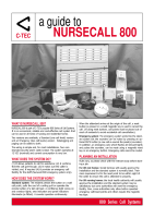
Use four core stranded security alarm cable (7/0.2) for each zone or
sounder (this will leave approx. 25% spare cores in most cable runs).
Zones may be wired to the nearest panel on which they are
indicated (see example wiring configurations for typical bedroom
layouts - fig. 1 below).
If multi-core cable is used you need one common wire (two for
the emergency system), plus one wire per zone or sounder, plus
25% spares. Therefore, on an emergency system, seven zones need
2 +7 (=9) +25% =12 cores.
Voltage drop is not normally a problem on standard systems, but
may be on emergency systems where cable runs exceed 50 metres.
Use four cores between standard master and repeater panels, plus
one per zone being indicated, plus 25% spares.
Use five cores between emergency master and repeater panels,
(two of which should be 1.0 mm to minimise voltage drop), plus
one per zone being indicated, plus 25% spares.
Fig. 1: Example wiring configurations for typical bedroom layouts.
Standard indicator panels have
a light grey fascia with white
spaces for labelling (use an
electronic 9mm labeller such
as Brother's PT system).
10, 20, 30, 40, 50, 60, 70, 80
and 90 zone versions are usually available ex-stock with larger
sizes available to order. The cabinet, which is constructed of
black metal, is designed to be surface mounted and includes a
regulated power supply to charge a 12V 2.1AHr back-up battery
(not supplied). Each panel incorporates one zonal alarm LED
per zone, an integral buzzer and a supply healthy LED.
All panels measure 406mm wide x 83mm deep. 10-30 zone
panels are 191mm high, 40-60 zone panels are 380mm high
and 70-90 zone panels are 565mm high.
4 core
4 core
4 core
C
4 core
4 core
C
4 core
4 core
C
4 core
to
other
zones
)
ceiling
pull
call
point
overdoor
light
overdoor
light
ceiling
pull
call
point
call
point
ceiling
pull
indicator
panel
4 core