
Total Solution to Earthing & Lightning Protection |
9AKK106354A3360
10/15
10
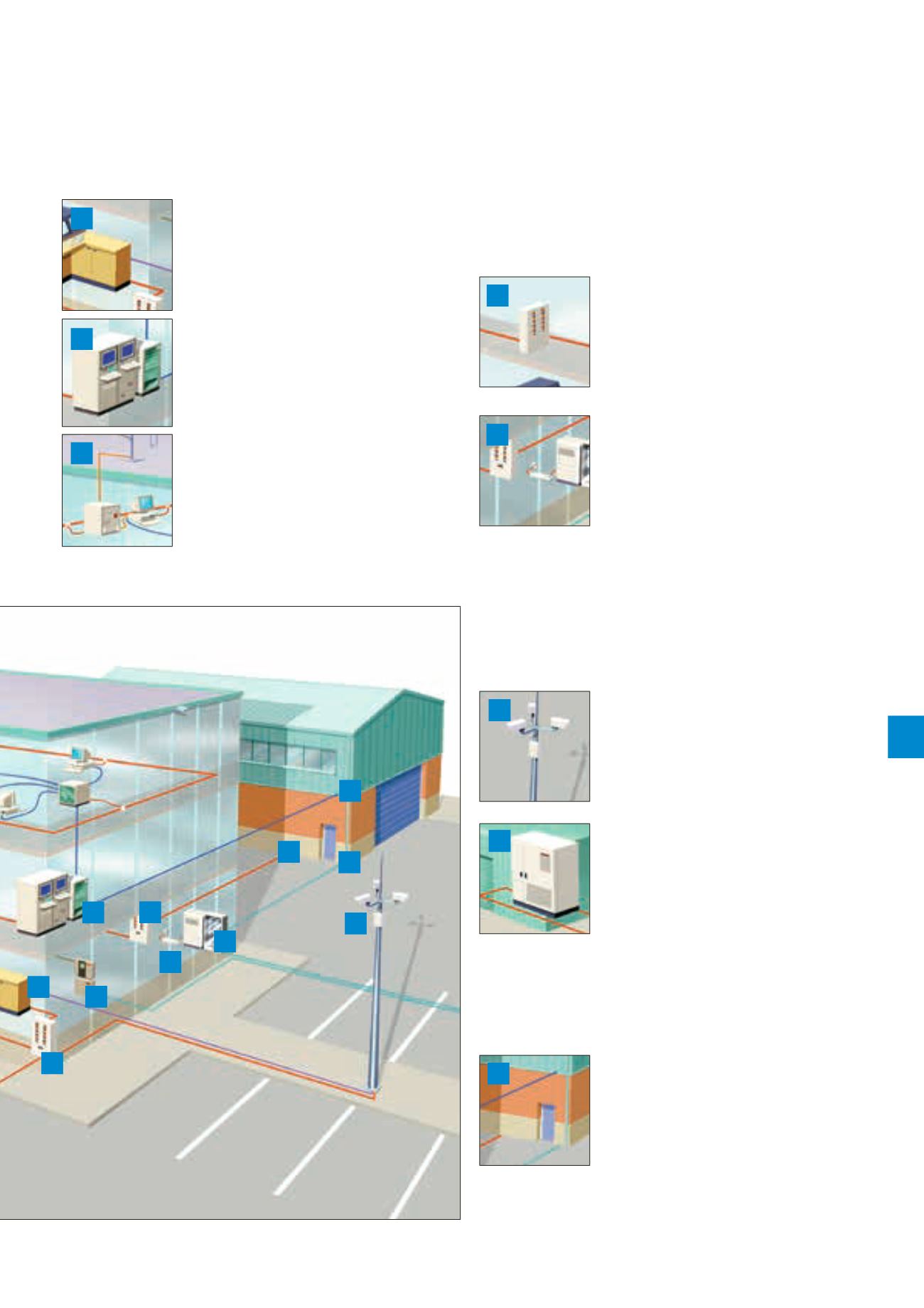
Protect electronic equipment
outside the building
Electronic equipment outside the main building in ancillary
buildings, on site or in the field should also be protected.
CCTV cameras
Protect outdoor CCTV cameras with
protectors on the power supply, and
video cable (and, if relevant, telemetry
control line).
External buildings
If the UPS is housed in a separate
building with a separate earth, incoming
and outgoing supplies will need to be
protected. This is because most modern
UPS systems contain electronics that
make them vulnerable to being disabled
by transient overvoltages. To prevent
transient overvoltage damage to the UPS it must have a
protector installed on both its input and output (outgoing the
building). A protector will also need to be installed on the
power supply into the main building (2).
Data communication/telephone lines
Protection is also installed on mains
power, data communication and telephone
lines entering the neighbouring building.
Additional protection (not shown) may be
required within this building (whether it’s
a computer-controlled warehouse or
automated manufacturing operation with PLCs, drives and
computer controls).
Data & signal lines
Protectors are installed on CCTV video
cables from outdoor cameras to
prevent damage to the control desk.
A protector is installed at the network
hub to protect it from transients on
the between building data link.
Equipment such as our RF receiver,
with antenna (or satellite) links will
also need protecting.
Protect the power supply locally to
important equipment
Within the building transient overvoltages
can be injected on to the mains power
supply (downstream of the protector
at the incomer). Consequently, protectors
should be installed close to important
pieces of equipment.
CCTV cameras
Protect outdoor CCTV cameras with
protectors on the power supply, and
video cable (and, if relevant, telemetry
control line). The telephone PBX is
protected locally by a plug-in protector.
This illustration is designed to demonstrate the main aspects and
individual components of a system of Surge Protection methods. It is not
intended to represent an actual scheme conforming to a particular
code of practice. The drawing is not to scale.
3
4
5
6
7
11
8
12
14
14
14
7
9
8
12
14
13
10
11


