


 181 / 356

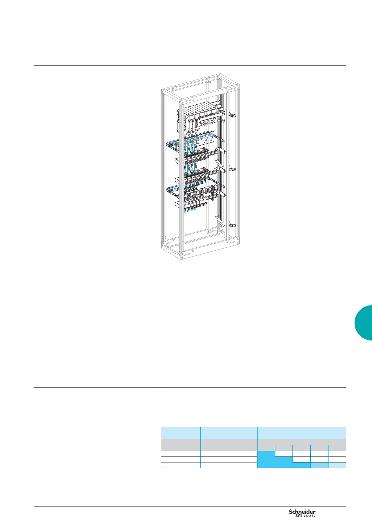
Distribution
Presentation
DD382627
The rear busbars are mounted directly on the uprights
of the framework.
There are three and four-pole versions with ratings
from 160 to 400 A.
Available in two lengths, 1000 and 1400 mm, they can
be cut as needed.
The connection with a Compact or Interpact incoming
device occupies two vertical modules (50 mm each).
Composition
Flat, copper bars with threaded M6 holes every 25 mm for connection along the
entire length of the busbars.
The insulating supports can receive a fifth bar, 15 x 5 mm or 20 x 5 mm, to create an
earth bar.
Installation
The busbars are mounted directly on the functional uprights of enclosures or on an
adapter (03595) in a cubicle.
Connection
16 mm² to 50 mm² flexible cables, with crimped lugs
insulated flexible bars (see page B-54).
Electrical characteristics
rated peak withstand current Ipk (kÂ)
30 k for 160 A busbars
40 k for 250 A busbars
55 k for 400 A busbars
rated insulation level Ui = 1000 V
b
b
b
-
-
-
b
Busbar calculation
Busbar size and distance between supports
The table below indicates:
the size of the bars to be used, depending on the permissible current level in the
busbars
the distance between supports, depending on the rated short-time withstand
current (Icw).
b
b
Rating
(A)
Size of bars
(mm)
Distance between support centres
(1)
(mm)
Icw
(kA rms / 1 s)
10
13
15
20
25
160
15 x 5
250
20 x 5
400
32 x 5
450
300 225
(1)
Multiclip 200 A distribution blocks equipped with connections (04029) can be used as
intermediate supports (200 mm max. distance between centres) in addition to the top and bottom
supports.
400 A rear busbars
Secondary distribution
B-43