


 123 / 338

A-71
Others
Human-switchboard interface
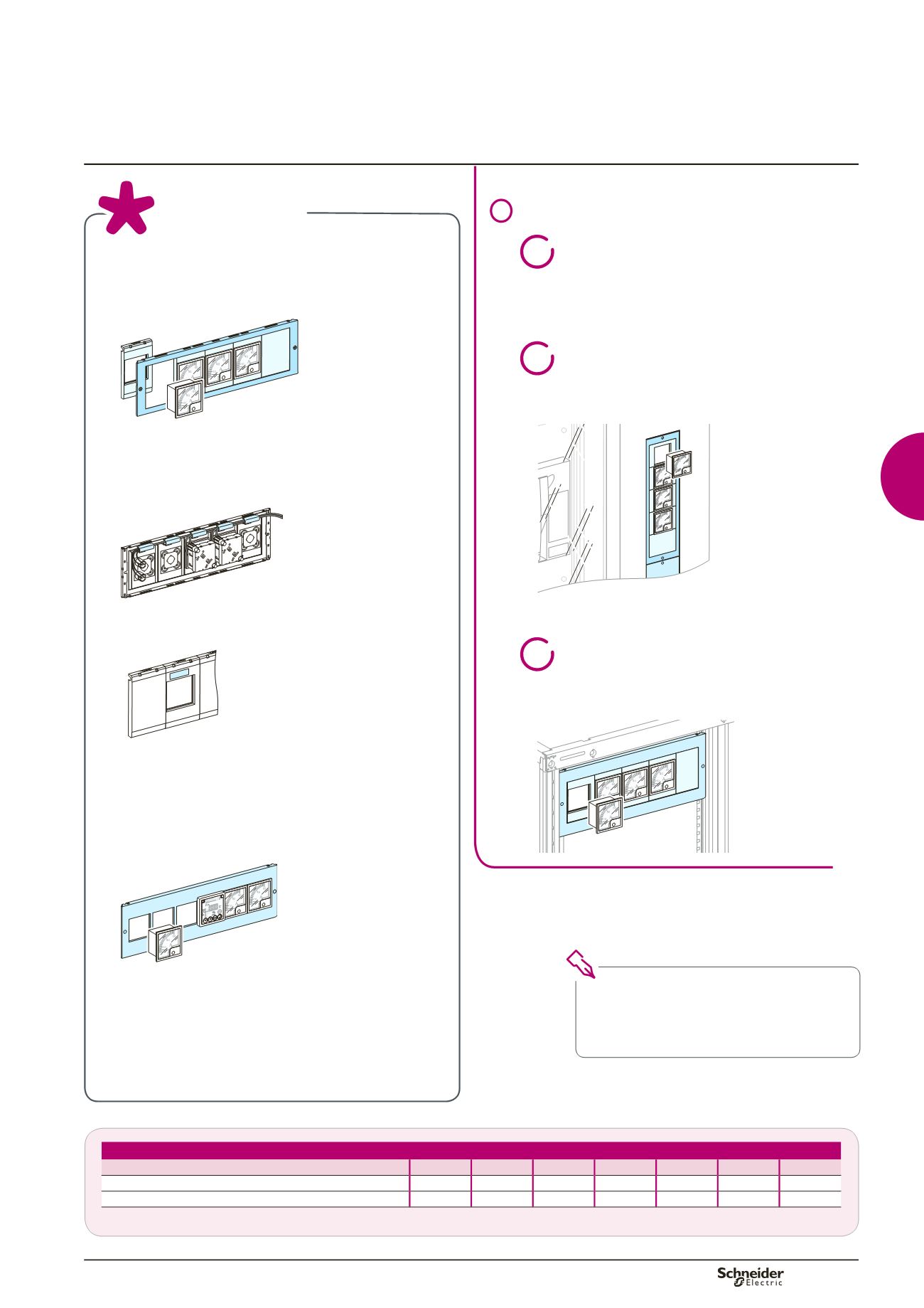
72 x 72 and 96 x 96 mm devices
Note:
to maintain the IP55 degree of protection,
the measurement devices must be installed
behind a transparent door.
If they are installed on a plain door, use the
corresponding mounting plates.
Installation in a switchboard
1
>
>
In the device zone of enclosures and cubicles,
like a front plate
2
>
>
On a door with cut-outs in a300or 400mmwide
cubicle
A
60
40
10
0
A
60
40
10
0
A
60
40
10
0
A
60
40
10
0
Dd381684.eps
3
>
>
On a plain door with cut-outs in wall-mounted
and floor-standing enclosures (except IP55).
Dd383642.eps
The degree of protection for installed devices is IP30.
Presentation
Device mounting
On an interface with plastic mounting plates,
H = 150 mm (3 modules)
Dd381705.eps
The interface is made up of a metal front plate and
plastic mounting plates that clip onto the front plate:
>
>
the devices are attached in the cut-outs of the plastic
mounting plates and insulated from the front plate
Dd381687.eps
>
>
a systemat the rear of themounting plates guides the
wires
Dd381688.eps
>
>
each mounting plate can receive an adhesive label
>
>
plain mounting plates are available to blank off any
unused locations.
On a metal front plate with cut-outs,
H = 150 mm (3 modules)
Dd381689.eps
>
>
Devices are attached directly to the metal front plate.
>
>
Blanking plates are available to blank off any unused
locations.
>
>
Economical solution.
Possible installation
Catalogue number
03904
03928
03910
03911
03913
03912
03914
CSP (08564, 08566)
b
b
b
b
b
b
b
L300/L400 with cut-out (08593, 08594)
b
b
b
b
b
-
-
Note:
device mounting on door: earthing braid (cat. no. 08910) or earthing wire (cat. no. 08911) mandatory.
Functional system
Functional units