


 115 / 338

A-63
Fupact ISFL
vertical / 3P
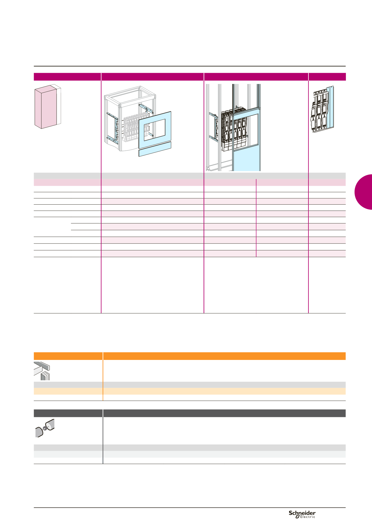
Determining the busbars
Fusegear
Mounting
Through cut-out front plate
Through a 2/3 cut-out front plate
Accessories
650 150
400
DD384443.EPS
DD384444.EPS
DD384445.EPS
Devices
ISFL160
ISFL160
ISFL250/400/630
Number of devices per row
9
10
5
-
Number of vertical modules
11
24
24
-
Mounting plates
03545
+
(1)
03546
+
(1)
03546
(1)
+
(2)
-
Length adapter
-
+
5 x
LV480870
(2)
-
-
Conversion kit for direct conn.
-
+
5 x
LV480854
(2)
-
-
Front plates
[No. of vertical
mod.]
with cut-out
03736
[11]
-
-
-
FAV 2/3
-
03735
[24]
03735
[24]
-
CSP 12 mod.
-
08562
08562
-
Side frame door cut-out
2 x
LV480868
2 x
LV480868
2 x
LV480868
-
Blanking plate
03740
03740
03741
(3)
-
Busbars cover
-
-
-
04860
Characteristics
b
The fuses are installed on the horizontal bars
which are in turn supported by a mounting plate
b
The front plates are secured to the hinged front
plate support frame.
b
The front may be covered either by a cover frame
or a plain or transparent door.
b
Current transformers can be installed behind ISFL
fuse-switch disconnectors.
b
The fuses are installed on the horizontal bars
which are in turn supported by a mounting plate
b
The front of the cubicle is made up of two parts:
v
2/3 cut-out front plate allowing introduction of the
fuses
v
1/3 front plate support frame (12 modules) on
which the functional units are mounted
b
The front may be covered either by a cover frame
or a plain or transparent door.
b
Current transformers can be installed behind ISFL
fuse-switch disconnectors.
(1)
The bars are made by the customer: for choice of bars, see pages B-12 to B-19.
(2)
Adaptation accessories LV480870 + LV480855 used to:
b
install two ISFL160 devices on a mounting plate 03546
b
mix ISFL devices.
(3)
Use 2 blanking plates per device.
Note:
for ISFL160, by fixing screws only.
Connection
Direct
Devices
ISFL160/630
Connection
By cables or directly on the busbars with clamp fixing or pressure fixing
Distribution
Devices
ISFL160/630
Downstream connection
With cable
Note:
for determining the busbar, see page D-60.
Functional system
Functional units