


 28 / 210

28
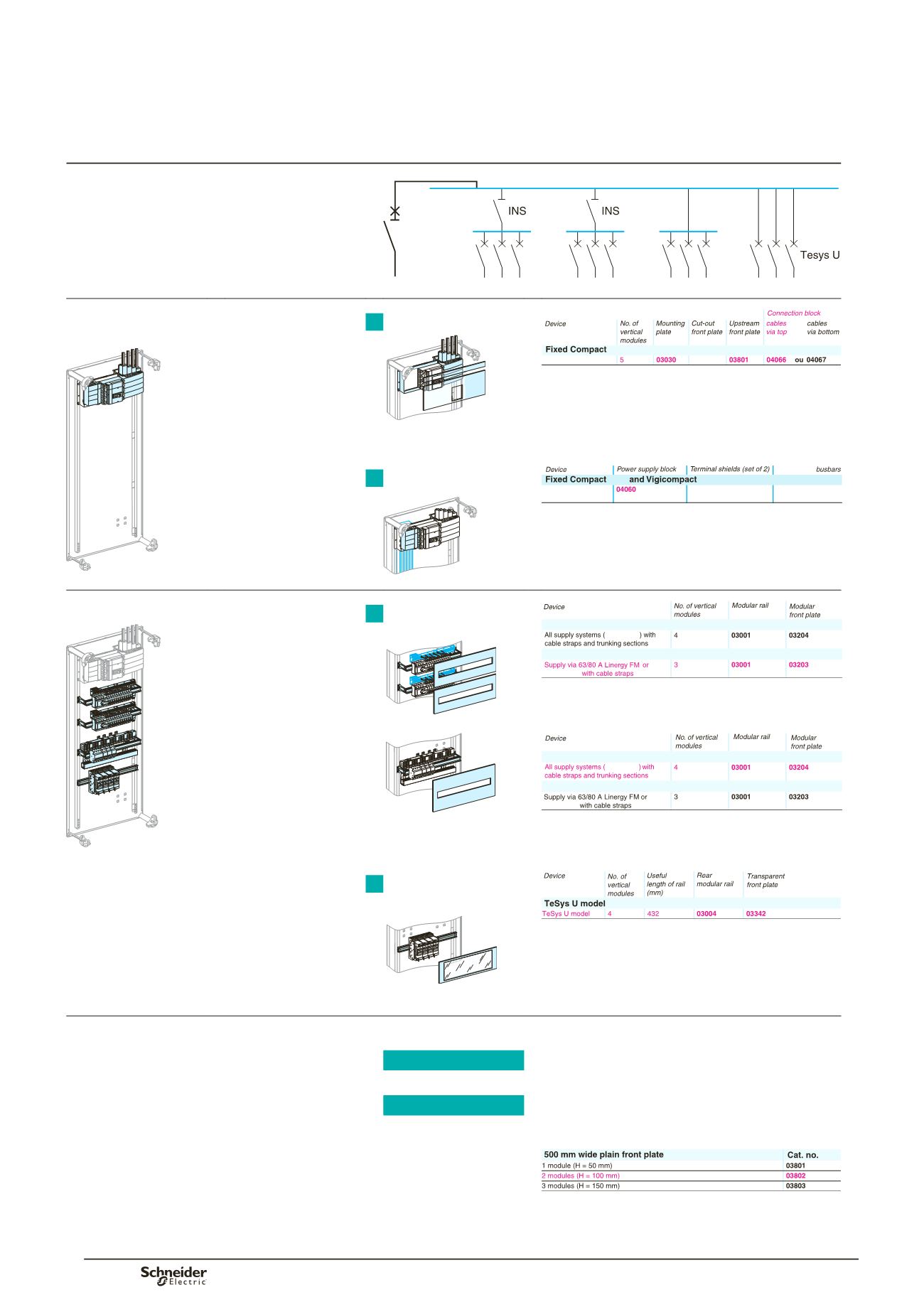
Starting with the electrical
diagram: IP30 switchboard
NSX250
C60
or
iC60
C60
or
iC60
C60
or
iC60
DD385258.eps
Install the incomer
Installation/connection
NSX100/250
03232
NSX
DD383960.eps
> see page 36
DD385295.eps
DD385294.eps
b
b
order the mounting
plates and the front plates
b
b
the incoming
connection block
b
b
the power supply block
for the Linergy BW
busbars.
Distribution using
Linergy BW busbars
NSX100/250
NSX
NSX
Linergy BW
DD385227.eps
DD381878.eps
Install the modular devices
Acti 9
> see page 55
All Multi 9 or Acti 9 devices
Multi 9 or Acti 9 devices
y
40 A
Linergy FH
Linergy FH
DD385228.eps
Dd385272.eps
Order the mounting
plates and front plates
taking into account:
b
b
supply to the rows
b
b
cable running.
Dd385271.eps
Dd383519.eps
All Multi 9 or Acti 9 devices
Multi 9 or Acti 9 devices
y
40 A
Linergy FH
Linergy FH
DD385229.eps
TeSys "U"
DD381978.eps
> see page 57
DD381880.eps
b
b
Linergy FM distribution block
> see page 96
b
b
Cable running
> see page 74
Determine the size of the switchboard
b
b
count the number
of occupied modules
19 modules
b
b
determine the
corresponding
wall-mount enclosure
21 modules
b
b
order the additional
plain front plate.
Plain front plate
DD381979.eps
> see page 68
1
2
1
2
Determiningcataloguenumbers
Presentation