


 175 / 182

D-34
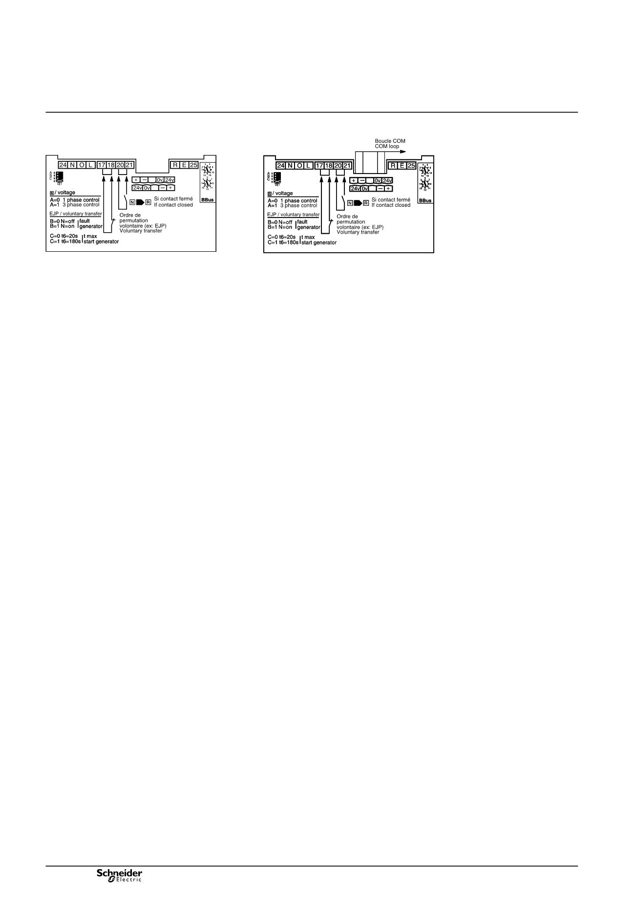
Electrical diagrams
Controller settings
Using communication functions
DB101762
DB101763
Tests on “Normal” source voltage
A = 0 single-phase test,
A = 1 three-phase test.
Voluntary transfert (e.g. for energy management)
action in the event of genset failure
b
b
B = 0 circuit breaker N opens,
B = 1 circuit breaker N remains closed.
maximum permissible genset startup time (T6)
b
b
C = 0 T = 120 s,
C = 1 T = 180 s.
After this time has elapsed, the genset is considered to
have failed.
The address of the UA 150 controller is set using
the two BBus dials.
Controller settings