


 137 / 148


D-10
Electrical diagrams
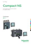
Connection of circuit breakers to the Modbus communication network
DB401596
Compact NS630b to 3200
Communication
40
100
%
%
Ø5...8
manu
auto
40
100
%
%
24 V
c
Compact NSX160
+ BSCM
Compact NSX400 + BSCM
+ communicating motor mechanism
Compact NSX160
Compact NS630b
(fixed device)
Masterpact NT
(withdrawable device)
3
1
2
4
5
Ethernet
6
7
7
8
9
9
10
10
Modbus 24 V
c
1
External 24 V
c
power supply module (AD)
2
Ethernet gateway (EGX100)
3
Modbus Communication Interface Module
(TRV00210) with stacking accessory
(TRV00217)
4
Modbus network
5
ULP cable
6
FDM121 display (TRV00121)
7
Compact NSX cord (LV434200, LV434201,
LV434202)
8
Modbus CCM “chassis”
9
Breaker ULP cord (LV434195, LV434196,
LV434197)
10
Modbus BCM ULP “device”