


 386 / 576

386
DB300006
Spacial EMCsolution
Electromagnetic protected
steel enclosures
Introduction
General
The increasing presence of electromagnetic interference in industrial environments,
together with the use of equipment susceptible to such interference requires the use
of suitably protected enclosures.
In order to suppress electromagnetic interference, S3HF enclosures, due to the type
of sheet metal and special gaskets used, fulfil two functions:
b
b
Provision of adequate screening, with the effectiveness of a Faraday cage.
b
b
Ability to provide effective protection of sensitive equipment by using galvanised
sheet metal chassis, and by following recommended installation procedures.
Electromagnetic interference
Electromagnetic disruptions comprises an electrical field E generated by a differing
potentials, and a magnetic field M, caused by current circulation, which combine
to form electromagnetic field.
The electromagnetic interference or "noise" is a disruptive electrical signal which
affects the useful signal and it likely to cause a malfunction.
Interference can be carried through the conductors or emitted through the
environment.
Main sources of electrical interference and equipment
sensitive to it
b
b
Programmable controllers.
b
b
Electronic circuits or boards.
b
b
Regulators.
b
b
Input signal cables (detectors, sensors, measurement probes).
b
b
Analogue signal cables.
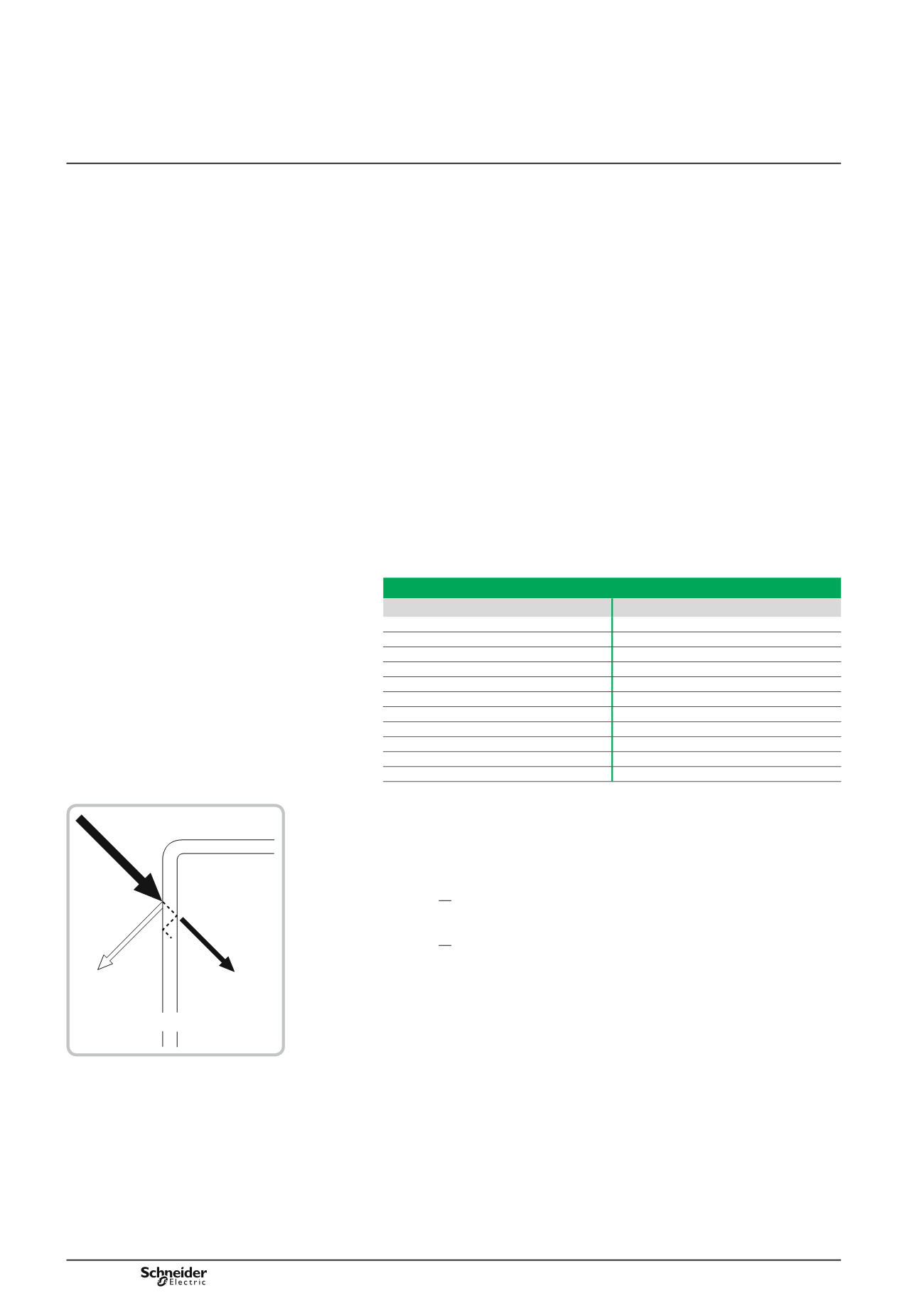
Attenuation level of EMC fields
The waves of electrical or magnetic fields are reflected when they meet the sheet
metal of the enclosure.
The effective rate of the screening or dampening "a" of the incident wave is
measured in decibels (dB) using the following formulae:
a = 20 log E
0
E
1
(dB) for electrical fields,
a = 20 log H
0
H
1
(dB) for magnetic fields,
b
b
E
0
and E
1
are the current values of the electrical field, before entering and after
entering the enclosure respectively.
b
b
H
0
and H
1
are the magnetic field values.
Main sources of electrical interference
Material
Frequency range
Motors
10 kHz… 100 MHz
Transformers/rectifiers
10 kHz… 100 MHz
Inductive load switching
50 kHz… 10 MHz
Spot welders
10 kHz… 50 MHz
Fluorescent lamps
100 kHz… 3 MHz
Relays, contactors
10 kHz… 200 MHz
Switching power sources
10 kHz… 30 MHz
Computers (internal clock)
50 kHz… 200 MHz
Variable speed drives
10 kHz… 100 MHz
Induction furnaces
0… 10 kHz
Power cables, etc.
0… 10 kHz
Reflected
wave
Enclosure surface
Outside
Inside
Incident
wave
Radiated
wave