


 7 / 8
7 / 8

07
Elegance Aluminium
A
ccessory boxes
• Remove appropriate knockout and
clip box into trunking base.
• For boxes in same compartment as
supply, remove appropriate knockout
and clip box into trunking base.
• When boxes are installed
consecutively, a 14mm wide length of
cover is required to cover the space
between the boxes.
• Part M box assemblies with
contrasting coloured faceplates are
available to meet the requirements of
DDA regulations for Visual Impairment.
C
overs
Covers are designed to limit
unauthorised removal and to remain in
position during normal conditions
irrespective of impact and minor
undulations of the mounting surface.
C
overs – fitting
Covers are clipped into place from front.
If accessory boxes are installed, the
LTL1/LP1010 cover is butt-joined to the
edge of the box (ESSB1/2 only). Cut
edges of the cover are concealed by the
accessory.
C
overs – removal
To remove a cover, first detach an
accessory to gain access. The main cover
can then be gently eased off the base.
S
creening
Aluminium containment will protect all
internal circuits from external
electromagnetic interference. For
internal segregation metallic dividing
fillets are avaliable.
O
ffset dimensions
The minimum set that can be
accommodated in the same plane (from
internal to external bend), is 145mm.
Dimensions
Elegance 110
A = 5254mm
2
total area
A = 2365mm
2
45%
space factor
With box in comp 1
A = 2987mm
2
total area
A = 1344mm
2
45%
space factor
E
legance 170
A = 1764mm² total area
A = 794mm² 45% space
factor
Without Accessory
B = 4508mm² total area
B = 2028mm² 45% space
factor
With Accessory
B – 1748mm² total area
B = 787mm² 45% space
factor
Cable capacities
• All calculations allow for a 45% space
factor.
As there can be differences between data
cable sizes, Marshall-Tufflex recommend
that cable dimensions are confirmed with
the manufacturing company.
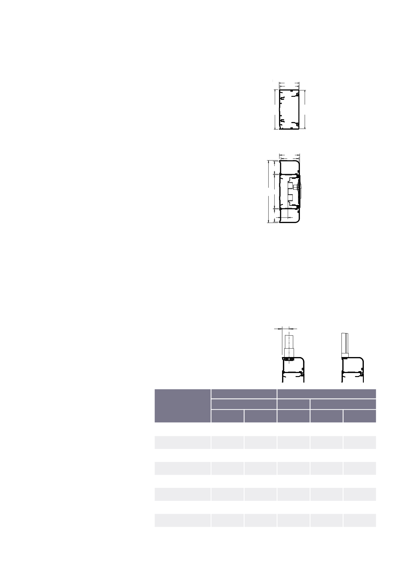
Fixing to Conduit and Mini Trunking
Elegance 170 can be used in
conjunction with Conduit and Mini
trunking systems as detailed in the
diagrams below:
Material
Aluminium trunking is manufactured from
high precision extruded aluminium with a
powder coat finish.
White RAL 9016
Silver Grey RAL 9006
Installation
Positioning
Elegance can be installed at dado level
or as a bench-mounted installation.
Fitting
• Secure trunking base every 750mm.
• Secure using No.8 round head
screws and washers using the grooves
in the outer (110) or inner (170)
compartments of the base to facilitate
drilling Ø6mm holes.
• Avoid over-tightening to permit thermal
movement.
• The use of plastic caps over screw
heads is recommended to protect
installed cables.
• To cut the trunking, use a fine tooth
blade (32/36tpi) or, preferably, a
circular saw with a 350mm diameter
fine tungsten blade (90/108tpi). This
will produce an edge requiring minimal
de-burring.
• Consecutive lengths of base are
aligned and butt jointed together.
E
arthing
• Base, covers and metallic fittings to be
cleaned of protective powder coatings
for earth bonding.
• Elegance 110. Incoming earth
connection is made using LBT1
bonding assembly installed in the earth
channel of the base.
• Elegance 170. Incoming earth
connection is made using LBT3 bonding
kit, with edge clip attached to the earth
rib in the base and faston connector
crimped to incoming earth cable.
• Bonding base to base: in final ring or
radial 32Amp circuits, bonding strap
LBS1 can be used.
• Bonding end caps to base: use
bonding strap LBS5.
• Bonding base to cover, use LBS2.
Joints and bends
• Straight lengths should be butt jointed
together with the aid of LDP1 coupler
pin if required.
• Internal bends, external bends, flat
angles and tees are prefabricated in
aluminium and butt jointed together so
cutting of base and covers has to be
very accurate to produce a good finish.
Technical Information
Cable capacity chart
Total cables =
Volume/cable factor
Elegance 110
Elegance 170
Compartment A
CompartmentA
CompartmentB
No box
Withbox
No box
Withbox
PVC power cable 1.5mmv
stranded copper
275
–
92
236
92
PVC power cable 2.5mm
2
stranded copper
188
–
63
161
62
PVC power cable 4.0mm
2
stranded copper
142
–
48
122
47
PVC power cable 6.0mm
2
stranded copper
112
–
37
96
37
Data cable: Ø5.5mm
76
–
26
65
25
Data cable: Ø6.0mm
64
–
21
55
21
Data cable: Ø6.5mm
54
18
46
18
Data cable: Ø7.0mm
48
16
41
16
55.5
55.5
107
110
52
49
19
36
36
92
170
17.5