


 108 / 210

108
n
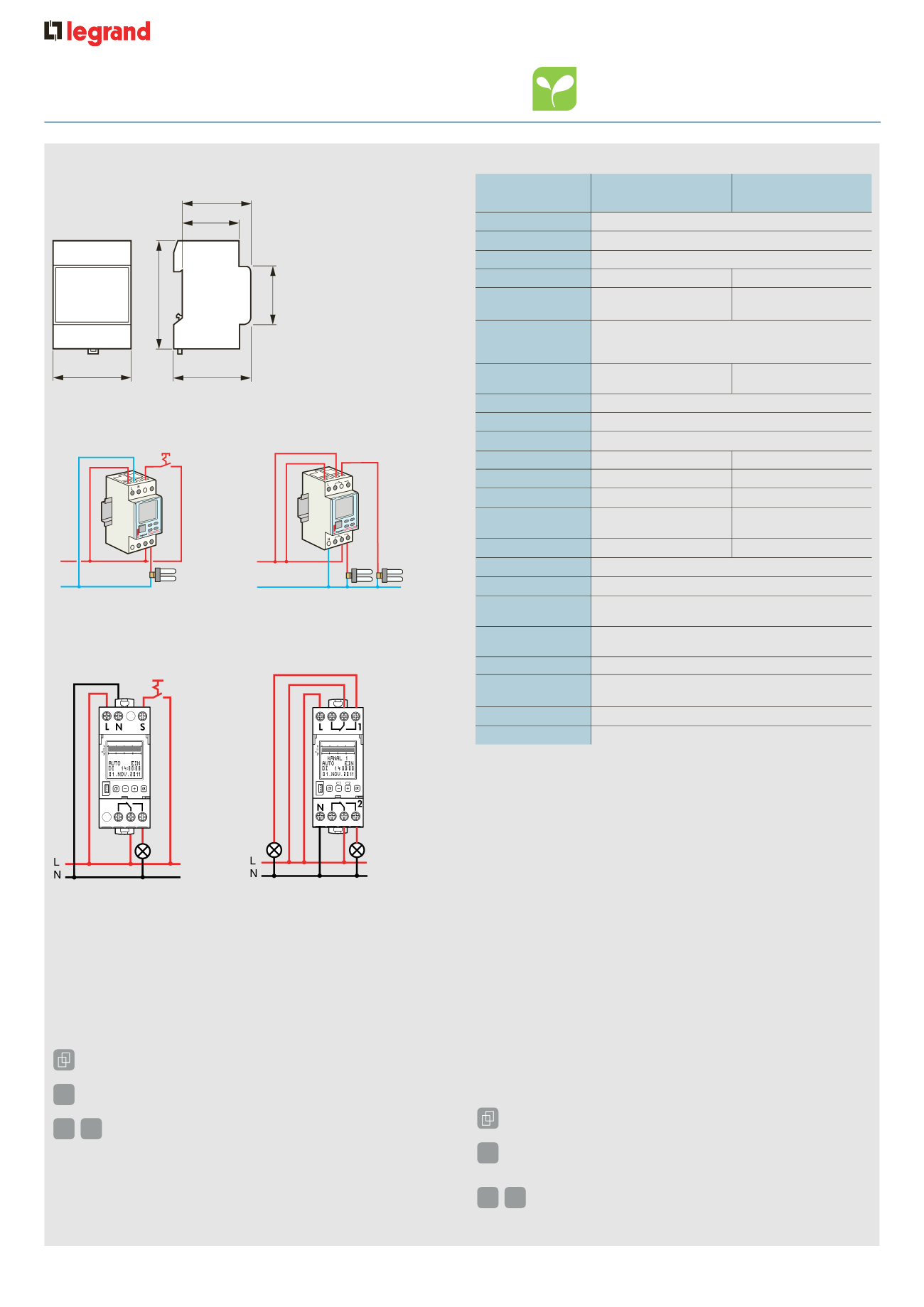
Wiring diagrams
Cat. No. 4126 54
Cat. No. 4126 57
45
44
60
83
66
35 . 6
3
L
N
L
N
2
1
4
2
1
4
Output closing and breaking times are calculated based on the date,
the actual time when the device was switched and on geographical
coordinates of the actual location
n
Technical information
Type
AlphaRex
3
Astro D21
AlphaRex
3
Astro D22
Cat. No.
4126 54
4126 57
Supply voltage
230 V
±
Frequency
50/60 Hz
Programme
24 hour or 7 day
No. of channels
1
2
Effective power
1 W
1 . 5 W
consumption
Switching
capacity :
cos
ϕ
= 1
16 A 250 V
±
Contact
1 changeover
2 changeover
switch
switches
Min. prog. settting
1 second
Accuracy
±0 . 1 seconds per day
Terminal capacity
Single strand 1 . 5 to 4mm
2
Programmes
56
28 per channel
Control-cable length
Max. 50 m
Control signal
230 V AC/2 mA
Control-pulse
duration
100 to 200 ms
Delay time
0 to 23 h 59 min 59 s
Local coordinates
Resolution 1°/1' in EXPERT-Mode
Working reserve
1
5 years
Programme
memory
EEPROM
Summer/Winter
time
Auto
IP rating
IP 20
No. of 17 . 5 mm
modules
2
Operating temp.
–20 °C to +55 °C
Storage temp.
–20 °C to +60 °C
1 : For time and date only
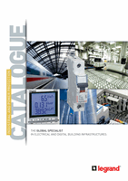
n
Dimensions (mm)
Cat. Nos. 4126 54/57
n
General information
Cat. No. 4126 54
Cat. No. 4126 57
AlphaRex
3
Astro D21
Cat. No. 4126 54
AlphaRex
3
Astro D22
Cat. No. 4126 57
• Start-up :
after applying the supply voltage, the time switch starts
automatically with the last selected function. The relay position is
set by the current programme
• Battery backup
- Backlighting
not active
- Data key
READ/WRITE only via the menu
• Start-up :
after applying the supply voltage, the time switch starts
automatically with the last selected function. The relay position is
set by the current programme
• Battery backup
- Backlighting
not active
- Data key
READ/WRITE only via the menu
• For safety :
when the time switch is connected to the mains supply
the contact should not be used on an isolated low voltage supply
and when the time switch is connected to the isolated voltage
supply the contact should not be used on the mains supply
OK
OK
-
-
+
+
Select menu, back to main menu,
Hold down > 1s = operating display
Select menu, back to main menu,
Hold down > 1s = operating display
Confirm selection or load parameters
Confirm selection or load parameters
Select menu options or set parameters
• Select menu options or set parameters
• Channel selection
C1 C2
0 6 12 16 24
0 6 12 16 24
2
4 1
AlphaRex
3
Astro programmable time switches
light control – digital for rail
4