


 61 / 244

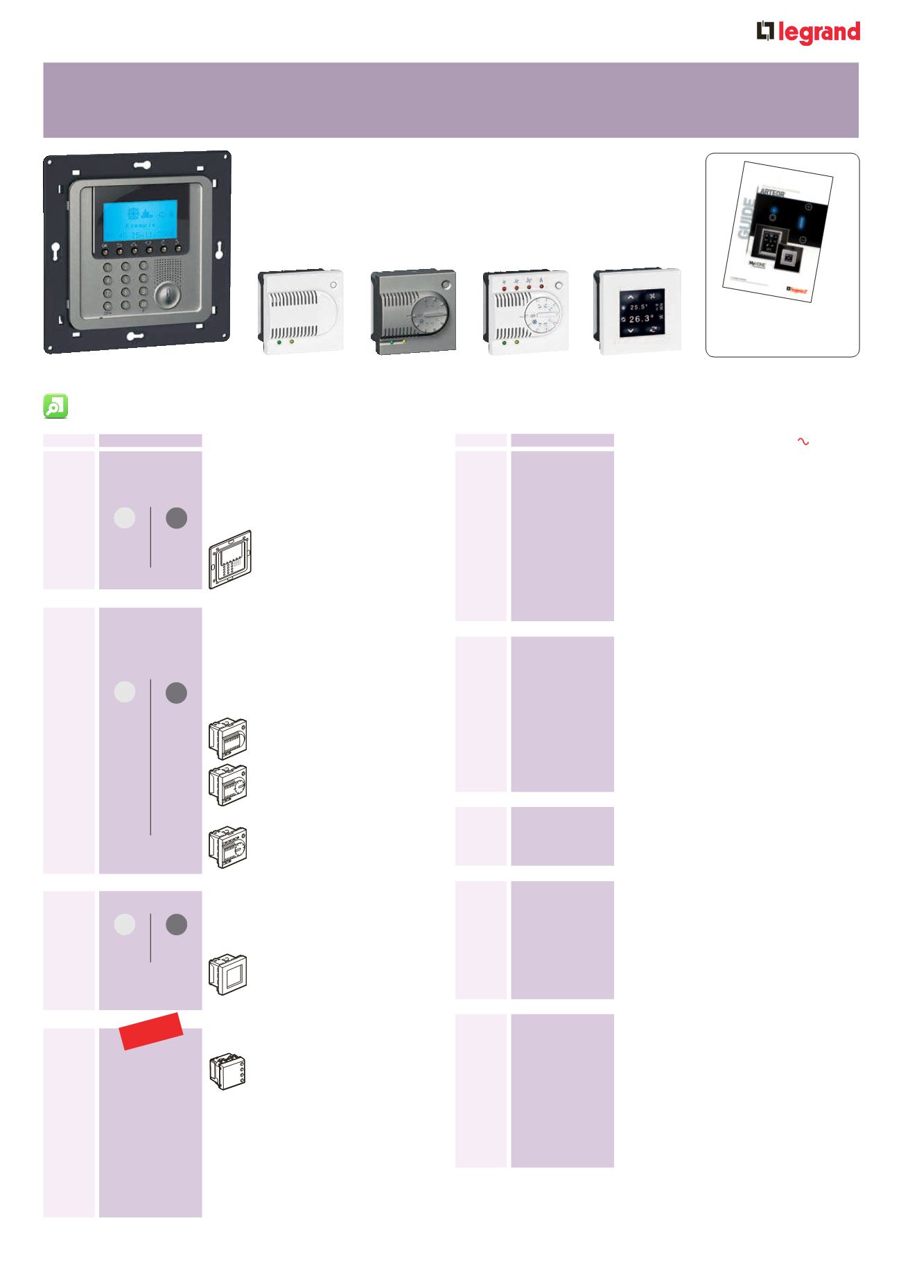
Arteor
TM
BUS/SCS
temperature control
ac
at os
entral units or temperature
control
uipped with white or magnesium suare
version eypad cover plates to be
euipped with special surround plates
(p
Supplied with support frame flush mounting
box and 2 battery
at o
Temperature control central unit
an manage up to ones
roes
To control the room temperature of heating
and cooling system
uipped with white or magnesium suare
version cover plates to be euipped with
surround plates (p
To be installed in flush mounting boxes
hite
agnesium
2 module mechanisms 22 x mm
2 2
Temperature setting range :
from ° to °
22 2
Temperature setting range :
from ° to ° with dial for
adustment of ° relative to
the set temperature and for the
modality selection
2 2
Temperature setting range :
from ° to ° with manual
automatic speed selection for
fancoil
SS cales
2 wire cable for BUS system
onform to and 2 2
ength m Supplied on wooden reels
eplaces at o 2
ength m Supplied on wooden reels
eplaces at o 2 2
ength m Supplied on wooden reels
eplaces at o 2 2
I transmitter or splitter
or controlling splitters in different modes
(autohot cold
anagement of nff speeds
(autolowmedium or high
Temperature range between °
Air conditioning remote control can “learn”
the signal
an be installed behind the air
conditioning unit
Supplied complete with 2 m cable
eplaces at o
US poer supplies
27 V
=
1 . 2 A
A£
nput voltage : 2
A
output voltage 2
=
aximum consumption : mA
aximum current supplied : 2 A
£ modules mm
eplaces at o
27 V
=
0 . A
nput voltage : 2
A
output voltage 2
=
aximum current supplied : A
2 £ modules mm
attery or temperature control
central unit
2 battery for central unit
eplaces at o
lu in umpers (p ac
at os
I rail actuators 10020 V
A
00
Actuator it 2 independent relays
2
or single and double loads :
A resistive
A motorised valves and pumps
2 £ modules mm
eplaces at o
Actuator it independent relays
or single double or mixed loads :
A resistive
A motorised valves pumps and fancoils
2 £ modules mm
eplaces at o
2
2
2
hite
agnesium
ouc screens
uipped with white or magnesium
surround to be euipped with surround
plates (p
2¤ £ touch screen for
management of max functions
sound system temperature control
scenarios energy management
2 module plates
hite
agnesium
1
Support frames and surround plates selection charts p. 30 31Technical information : wwwlegrandcouarteorbuildingautomation and follow the lin to ‘Arteor proect and technical guide’
ull technical guide
available to download at
.lerand.co.u
isplay t ermostat
lush mounted thermostat with
baclit display an be used
to control the temperature of
an individual one both if a
temperature central unit is and is not
present eatures a temperature probe and
an input for the connection of a contact line
(eg window contact an be used for the
management of different types of systems
and the adustment of the fan speed when
fan coils are used ossibility of automatic
operation (summerwinter with compatible
systems onnection to SS BUS
– 2 modules
Availale
Septemer 2013