
Arteor
TM
BUS/SCS
lighting control and automation
n
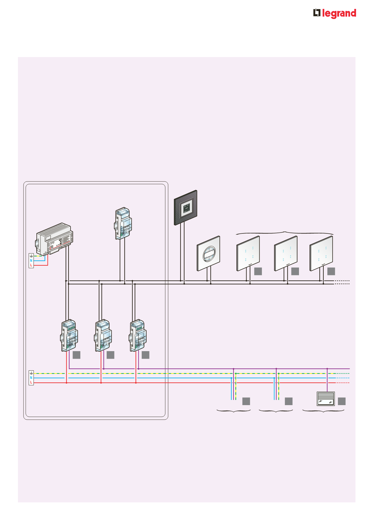
System principle
The lighting control system allows the management of different functions in a simultaneous and integrated way
All the components of the lighting control system are interconnected via an electronic circuit that can be programmed : the BUS
The information is exchanged through the 2 wire BUS cable at low voltage (2
=
There are two types of devices in the system :
the controls units which are connected only to the BUS cable and
the actuators connected both to the BUS cable and to the 2
A
power line for managing the connected load
hen the lighting control system devices are configured properly it is possible to manage the load as follows :
control for a single load
control for one or more load groups
simultaneous management of all loads
t is also possible to carry out special functions which are hard to achieve with conventional electrical systems
These functions are called scenarios
ne scenario is a set of simultaneous control of multiple groups of loads used in order to modify the environment according to the user’s needs
An example of a scenario can be represented by the simultaneous activation of lights which can be set by the user after getting inside the
building by using one single control device or by using the touch screen menu
n
Installation principle
Consumer unit
Power supply
Scenario controller
Cat. No. 5739 02
or 5739 03
Scenario module
Cat. No. F420
Touch control mechanism
Cat. No. 5739 04 or 5739 05
Touch screen
Cat. No. 5737 16
or 5737 17
2 wire cale or S Cat. No. 4669
in rail
leadin trailin
ed e dimmer
Cat. No. 0026 22
in rail
actuator
Cat. No. F4111N
one 1
itchen
one 2
inin room
one 3
Shutter control
Scenario controllers
can mana e
one 1 2 and 3
in rail
actuator
Cat. No. F4112
Cat. No. 46CN
230
1
1
2
3
1
2
3
2
3
Control units
Actuators
Loads
i htin
source
i htin
source
oller
linds
shutters
17


