


 198 / 430

4.76
General Catalogue • Protection Devices • Technical
MCCBs, Moulded Case Switches
x250
10
6
10
4
10
5
10
7
10
8
10
9
10
2
10
3
10
4
10
5
I
2
t (x 10 A s)
6 2
100 A
250 A
IPF (kA)
0.1
1
10
100
Ip (kA)
100
10
1
0.1
IPF (kA)
0.8
0.5
0.3
0.25
0.7
0.9
0.01
0.1
1
10
100
1000
100
10
1
xIn (A)
Temps de déclenchement (s)
Déclenchement
à froid
Déclenchement
à chaud
(courant nominal)
0.001
10000
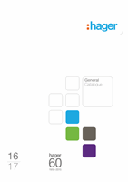
Tripping curve
MCCB x250
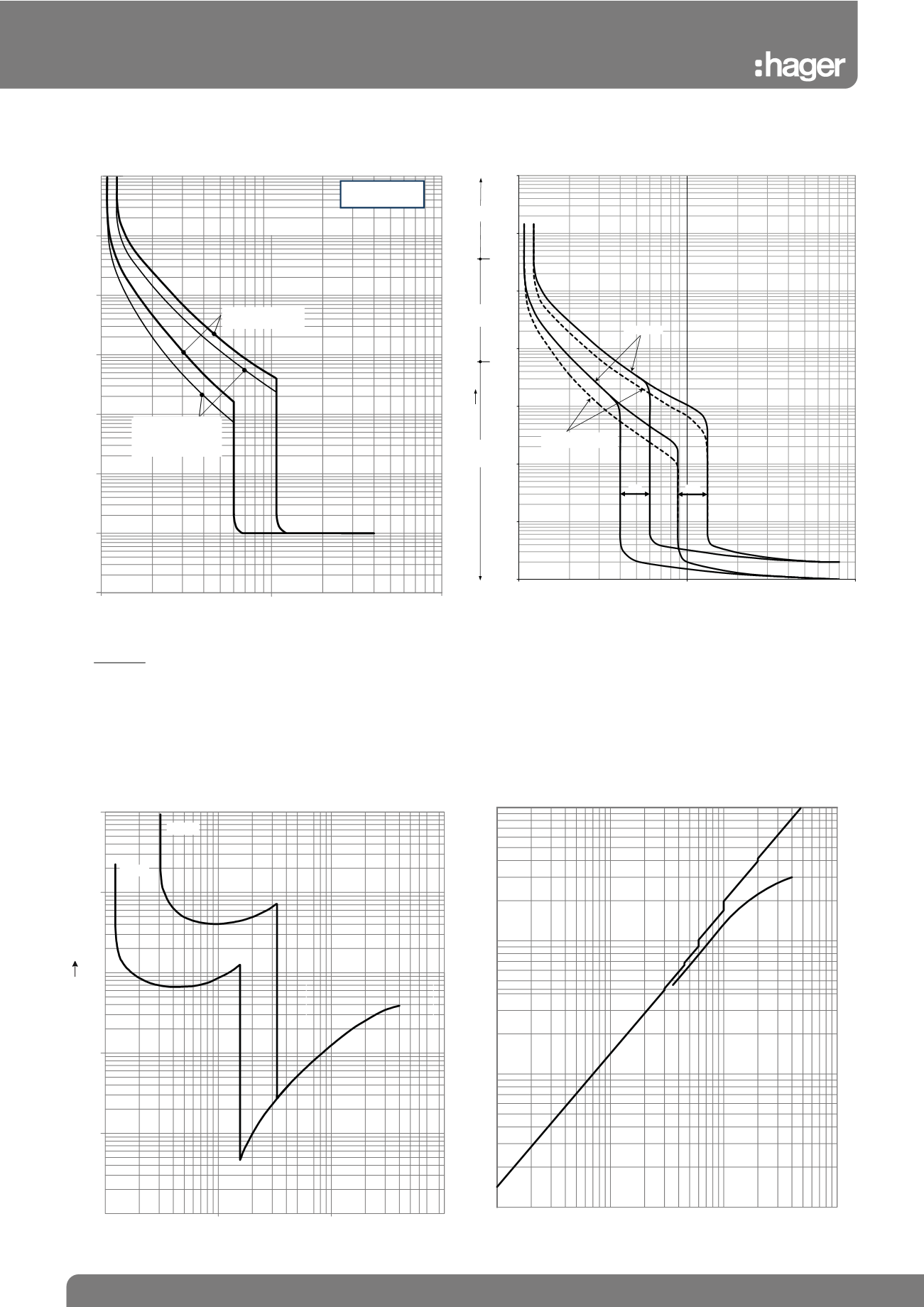
Thermal constraint curve at 400V (Let-through energy)
MCCB x250
Current limiting curve at 400V (Let-through peak current)
MCCB x250
Hot start
(rated current)
Cold start
Tripping time (s)
Tripping curve
MCCB h250 TM
0.01
0.1
1
10
100
1000
10000
100000
100
1000
10000
Tripping time (sec)
% In @ Tcal (A)
Fromcold state
Fromhot state
(75% ratedcurrent)
min.
max.
hour
minute
second
time
Instantaneous trip current:
up to 200A = 13 x In +/-20%
250A = 11 x In +/- 20%
Earth fault loop impedance (Zs) can be calculated from the formula
Zs ≤ 230x0.95
I a
Where I a = I n of MCCB x mag setting x 1.2