


 191 / 430

4.69
Sales Service Centre • 01952 675612 Technical Support Helpline • 01952 675689
MCCBs & Moulded Case Switches
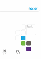
x160
Tripping curve
MCCB x160
MCCB Disconnection Data
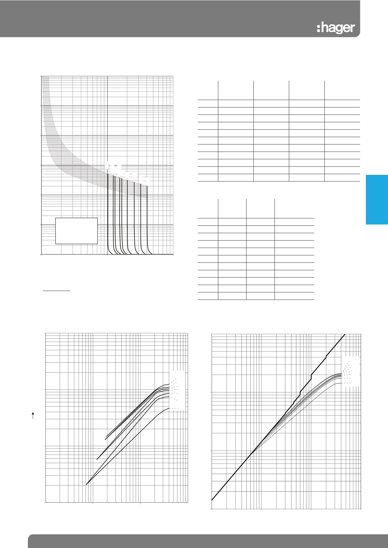
Thermal constraint curve at 400V (Let-through energy)
MCCB x160
Current limiting curve at 400V (Let-through peak current)
MCCB x160
16A
40A
63A
80A
100A
125A
160A
I
2
t (A s)
2
10
4
10
5
10
6
10
7
10
1
10
2
1
0.1
IPF (kA rms)
125A
0.8
0.5
0.3
0.25
0.7
0.9
16A
40A
63A
80A
100A
160A
0.1
1
10
100
10
10
1
0.1
IPF (kA rms)
Ip (kA)
1
2
0.01
0.1
1
10
100
1000
10000
1
10
100
Tripping time (sec)
x In @ Tcal (A)
160A
80A
100A, 40A
63A
32A
25A
20A
16A
125A, 50A
The magnetic
threshold trippting
curves is mean value.
The tripping area is
Irm ±20%
Earth Fault Loop Impedance Data
Disconnection time 0.2s, 0.4s, 1s
Device
rating
(A)
Instantane-
ous trip (xI n )
Instantane-
ous trip (A)
add 20%
tolerance (I a )
Zs = (230 x
0.95) / I a
16
40.3
644.8
773.8
0.28
20
32.2
644.0
773
0.28
25
25.7
643
771
0.28
32
20.13
644.2
773.0
0.28
40
15.0
600.0
720.0
0.30
50
12.0
600.0
720.0
0.30
63
16.6
1045.8
1255.0
0.17
80
13.1
1048.0
1258
0.17
100 15.4
1540.0
1848.0
0.12
126 12.3
1538
1845.0
0.12
160 10.22
1635.2
1962.2
0.11
Disconnection time 5s
Device
rating
(A)
trip (xI n )
I a (A)
Zs = (230 x
0.95) / I a
16
10
160
1.37
20
10
200
1.09
25
10
250
0.87
32
10
320
0.68
40
10
400
0.55
50
10
500
0.44
63
10
630
0.35
80
10
800
0.27
100 10
1000
0.22
125 10
1250
0.17
160 10
1600
0.14
The earth fault loop impedance requirements for larger devices can
be calculated by the formula given in BS7671:2008
Zs ≤ 230 x Cmin
l a
Where l a = I n of MCCB x Mag setting x 1.2
Protection
Devices