


 38 / 51

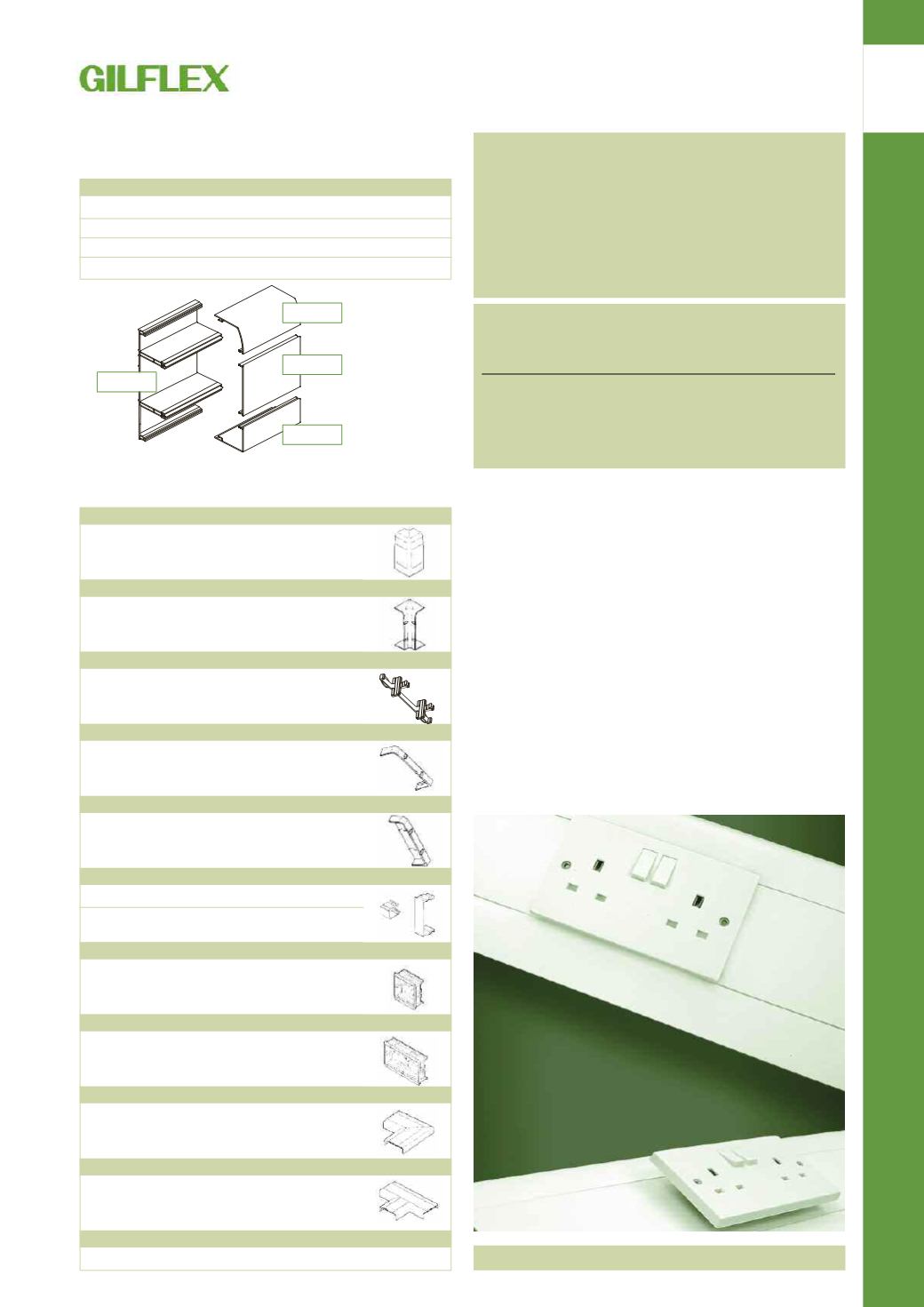
SYSTEM 38/48 TRUNKING
5
EXTERNAL CORNER
GX4801 WHI
Includes screws, screw caps and segregators
Each
INTERNAL CORNER
GX4802 WHI
Includes screws and screw caps
Each
BASE COUPLER
GX3808 WHI*
5
COVER JOINT
GX4811 WHI
Includes screws and screw caps
5
TRUNKING END CAP
GX4816 WHI
Left & right hand – Include screws and screw caps Pair
CABLE RETAINERS
GX3817 WHI* For top/bottom compartments
10
GX3818 WHI* For centre compartment
10
SINGLE ACCESSORY BOX
GX3821 WHI* Fixing Centre 60.3mm
25
25mm deep
TWIN ACCESSORY BOX
GX3822 WHI* Fixing Centre 120.6mm
10
25mm deep
FLAT ELBOW
GX4825 WHI
Fabricated Elbow
Each
FLAT TEE
GX4828 WHI
Fabricated Tee
Each
SPARES
GX3836*
Screw fixing kit
2 Caps, 4 Screws
Ref. No.
Detail
Std Pack
SKIRTING TRUNKING ACCESSORIES
SYSTEM 48 SKIRTING TRUNKING
SKIRTING TRUNKING COMPONENTS
GX3800B WHI*
Base Carrier
6m
GX3800C WHI*
Curved Lid
30m
GX3800F WHI*
Flat Lid (centre)
30m
GX4800S WHI
Square Lid
30m
Ref. No.
Detail
Std Pack
TECHNICAL INFORMATION
Service outlets are provided by the insertion of accessory boxes to replace short lengths of
the centre compartment cover. All services are mounted in the centre compartment using
GX3821 Single or GX3822 Twin Accessory boxes.
Moulded internal corners, external corners and jointing pieces are fixed to the trunking
body with countersunk self-tapping screws (these screws fix into the compartment
dividing webs and do not enter the cable compartments) after the installation of cabling,
accessory mounting and cover fitting. A base coupler and cover joint are required for every
trunking joint. Self-tapping screws (which are concealed by screw caps) also fix end caps
at the end of a trunking run.
Accessory boxes (GX3821 Single and GX3822 Twin) locate into the centre compartment.
The removal of a section of cover the same length as the accessory boxes (70mm for
GX3821; 135mm for GX3822) is required. The ends of the cut cover lengths must overlap
the ‘wings’ of the accessory boxes. The accessories mask the cut ends of the covers.
Cable clips (GX3817 Top/Bottom and GX38318 Centre) are available for fixing into the
compartments to retain cables within the trunking body.
CABLE CAPACITIES
To conform to the requirements of IEE Regulations, power cables must not occupy
more than 45% of the area available within a trunking section.
Profile
Trunking Size
mm
Compartment
45% Space factor mm
2
Dado
170 x 50
Centre
1530
Top/Bottom 652
Skirting
170 x 50
Centre
1530
Top
652
Bottom
703
Type of
Conductor cross
Factor
Conductor
sectional area mm
2
Solid
1.5
8.0
2.5
11.9
Stranded
1.5
8.6
2.5
12.6
4.0
16.6
6.0
21.2
10.0
35.3
For single-core PVC insulated cables in trunking.
For each cable to be used, obtain the cable factors from the table.
Add all factors together and compare with the capacities given.
Any trunking with a space factor equal or larger than that of the total cable factors will
satisfactorily accommodate the cables.
GX3800B
GX3800C
GX3800F
GX4800S
* Items are common to both Skirting and Dado Systems