
Switch Disconnectors
3LD Main Control and EMERGENCY-STOP Switches up to 250 A
Introduction
7/4
Siemens LV 10 · 2014
7
■
Design
Design of the contacts
Each switch has three adjacent contact elements
1)
. A fourth
leading contact for switching the N conductor, a continuous
PE terminal, an auxiliary switch (1 NO + 1 NC) can be fitted to
each side of the switch. The auxiliary switches operate as
leading contacts on opening. On opening, the NO contact
opens before the main contacts, so that a contactor carries the
switching capacity in the circuit and the maintenance or safety
switch switches at zero current. On closing, the auxiliary switch
switches later than or at the same time as the main contacts.
Construction of rotary operating mechanisms
The rotary operating mechanisms of the switches for front or
floor mounting are mounted on control cabinet doors, front or
side panels with four-hole or center-hole mounting with a stan-
dard diameter of 22.5 mm and operated from the outside. In their
Off position, they can be locked with up to three padlocks with a
hasp thickness of 8 mm. Controls with defeatable door-coupling
rotary operating mechanism are available in addition.
• Switch position indicator:
The switch position is clearly marked with direction arrows and
an "O" for OFF and a "I" for ON at the front.
• Switches for front mounting:
The switches for front mounting are connected directly to
the rotary operating mechanism through the fixing screws or -
in the case of center-hole mounting - a special-purpose
coupling.
• Switches for floor mounting:
The switches for floor mounting are snapped onto 35 mm
standard mounting rails according to EN 60715 or screw-
mounted on mounting plates. The actuators are connected to
the lower section of the switch through a door coupling, which
can be released in its zero position, and a 300 mm long switch
shaft. When the control cabinet door is open, the switch can
be protected against inadvertent operation by removing the
switch shaft from the lower section of the switch.
The mounting depth can be adapted to individual require-
ments by adjusting the switch shaft length.
• Switches for distribution board mounting:
The switches for distribution board mounting are suited for
operation in distribution boards and for switching inside
control cabinets or distributors. They have cap and mounting
dimensions according to DIN 43880 and can be fitted under
the same cover together with miniature circuit breakers. The
selector switches can be locked in their OFF position with up
to 2 padlocks with a hasp thickness of 6 mm.
• Switches in molded-plastic enclosure:
For surface mounting of individual main control and
EMERGENCY-STOP switches, molded plastic-enclosed
switches to degree of protection IP65 are used. The actuators
can be locked in their OFF position with three padlocks with a
hasp thickness of 8 mm.
The molded-plastic enclosures each contain an N and/or
a PE terminal.
1)
16 A versions have four contact elements; 3-pole changeover switches
and 6-pole main control switches have six contact elements.
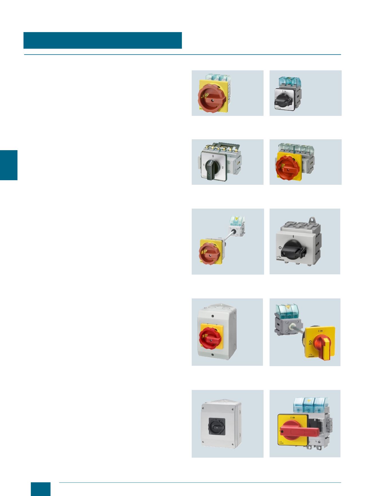
3LD2704-0TK53
switch for front mounting
with rotary operating mechanism
3LD2222-0TK1
switch for front mounting
with knob
3LD2122-7UK01 3-pole changeover
switch for front mounting with knob
3LD2103-3VK53 6-pole switch
for front mounting with rotary
operating mechanism
3LD2144-0TK53 switch for floor
mounting with rotary operating
mechanism and door coupling
3LD2530-0TK11 switch for
distribution board mounting
with knob
3LD2264-0TB5 switch in
molded-plastic enclosure
3LD2217-1TL13 switch for floor
mounting with rotary operating mech-
anism and defeatable door coupling
3LD2265-8VQ51-0AF6
solar plant isolator
3LD2418-0TK13 switch for floor
mounting, 250 A, with rotary operat-
ing mechanism and door coupling
© Siemens AG 2014


