
7
Switch Disconnectors
3KA, 3KE Switch Disconnectors up to 1000 A
Floor mounting
7/35
Siemens LV 10 · 2014
* You can order this quantity or a multiple thereof.
■
Application
3KA switch disconnectors are implemented as main control
switches and EMERGENCY-STOP switches for normal switching
duty and isolation of main circuits and auxiliary circuits. Another
field of application is the switching of induction motors and other
loads in the event of maintenance and repair.
Main control and EMERGENCY-STOP switches are manually
operated switch disconnectors according to IEC 60947-3 and
VDE 0660 Part 107 (EN 60947-3) and comply with the conditions
for switch disconnectors and the requirements of the machinery
directive EN 60204-1.
■
Selection and ordering data
All switch disconnectors with degree of protection IP00
Conductor connecting screws are generally included in the scope of supply
1)
Rated values reduced in the event of strong harmonics caused by
frequency converter operation.
For 8UC7 EMERGENCY-STOP door-coupling rotary operating
mechanisms (red handle, yellow indicator plate),
see Accessories.
Rated uninterrupted current
I
u
DT Article No.
Price
per PU
PU
(UNIT,
SET, M)
PS*
PG Weight
per PU
approx.
A
kg
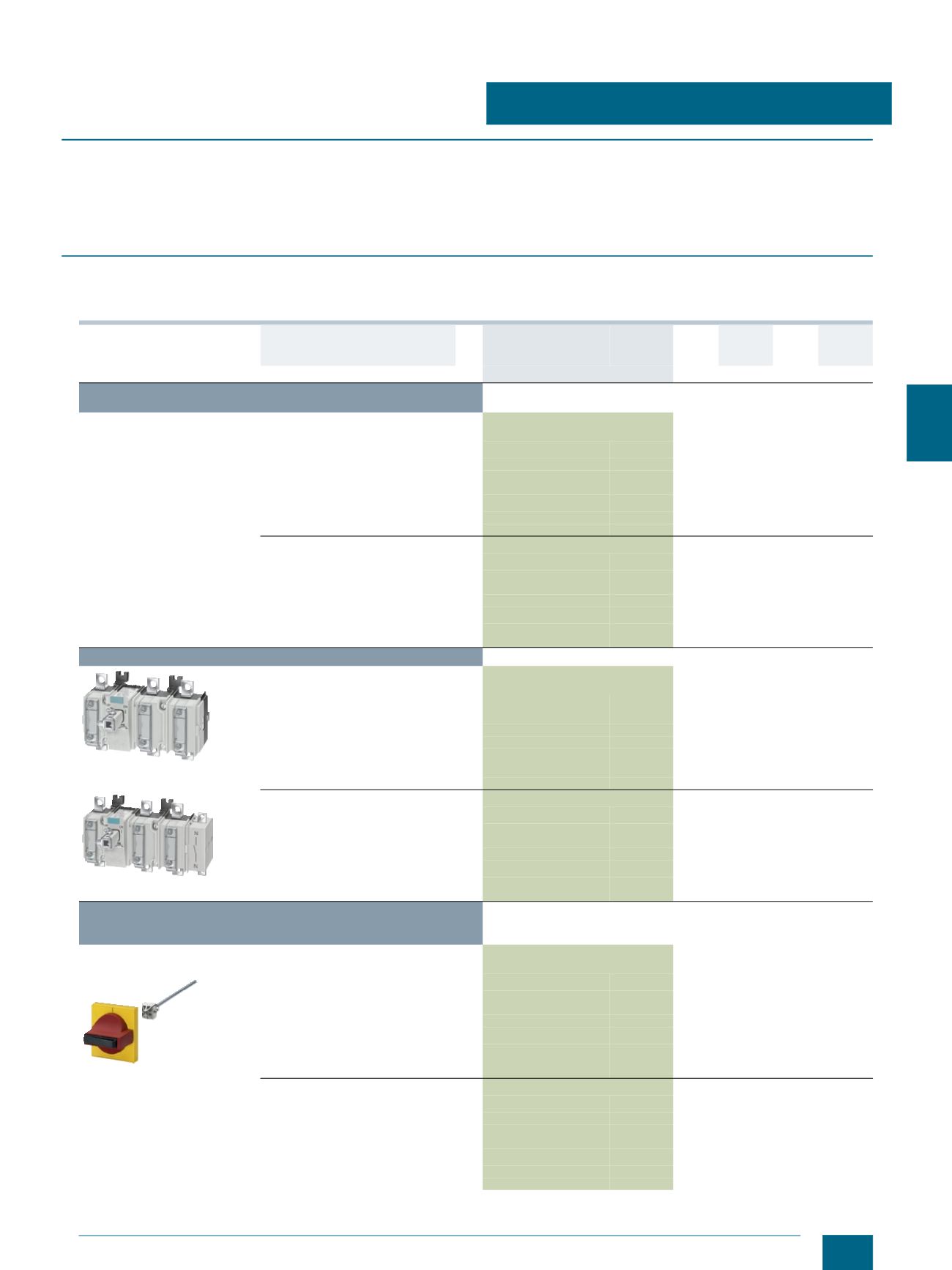
Complete versions with 8UC7 door-coupling rotary operating
mechanism (black handle)
3-pole for motor loads and for
power distribution
63
3KA5030-1GE01
1 1 unit
103 1.372
80
3KA5130-1GE01
1 1 unit
103 1.365
125
3KA5230-1GE01
1 1 unit
103 2.217
160
3KA5330-1GE01
1 1 unit
103 2.398
250
3KA5530-1GE01
1 1 unit
103 5.387
400
3KA5730-1GE01
1 1 unit
103 10.284
630
3KA5830-1GE01
1 1 unit
103 6.065
4-pole
1)
for power distribution
63
3KA5040-1GE01
1 1 unit
103 2.449
80
3KA5140-1GE01
1 1 unit
103 2.474
125
3KA5240-1GE01
1 1 unit
103 2.455
160
3KA5340-1GE01
1 1 unit
103 0.002
250
3KA5540-1GE01
1 1 unit
103 5.979
400
3KA5740-1GE01
1 1 unit
103 10.824
630
3KA5840-1GE01
1 1 unit
103 6.570
Basic switch versions without handle
3KA5330-1AE01
3-pole for motor loads and
for power distribution
63
3KA5030-1AE01
1 1 unit
103 0.905
80
3KA5130-1AE01
1 1 unit
103 0.903
125
3KA5230-1AE01
1 1 unit
103 1.874
160
}
3KA5330-1AE01
1 1 unit
103 1.997
250
3KA5530-1AE01
1 1 unit
103 4.450
400
3KA5730-1AE01
1 1 unit
103 4.582
630
3KA5830-1AE01
1 1 unit
103 5.096
3KA5340-1AE01
4-pole
1)
for power distribution
63
3KA5040-1AE01
1 1 unit
103 2.080
80
3KA5140-1AE01
1 1 unit
103 2.113
125
3KA5240-1AE01
1 1 unit
103 2.105
160
3KA5340-1AE01
1 1 unit
103 2.220
250
3KA5540-1AE01
1 1 unit
103 4.970
400
3KA5740-1AE01
1 1 unit
103 5.120
630
3KA5840-1AE01
1 1 unit
103 5.641
8UC7 EMERGENCY-STOP door-coupling rotary operating
mechanisms (red handle, yellow indicator plate)
for basic switch versions w/o handle
3-pole for motor loads and for
power distribution
8UC7121-3BB10
63
8UC7121-3BB10
1 1 unit
103 0.368
80
8UC7121-3BB10
1 1 unit
103 0.368
125
8UC7222-3BB20
1 1 unit
103 0.423
160
8UC7222-3BB20
1 1 unit
103 0.423
250
8UC7323-3BB30
1 1 unit
103 1.016
400
8UC7323-3BB30
1 1 unit
103 1.016
630
8UC7323-3BB30
1 1 unit
103 1.016
4-pole
1)
for power distribution
63
8UC7222-3BB20
1 1 unit
103 0.423
80
8UC7222-3BB20
1 1 unit
103 0.423
125
8UC7222-3BB20
1 1 unit
103 0.423
160
8UC7222-3BB20
1 1 unit
103 0.423
250
8UC7323-3BB30
1 1 unit
103 1.016
400
8UC7323-3BB30
1 1 unit
103 1.016
630
8UC7323-3BB30
1 1 unit
103 1.016
© Siemens AG 2014


