


 422 / 582

BETA Measuring
Three-Phase Measuring Devices
7
KT1 30 multimeters
11/6
Siemens ET B1 · 10/2008
11
■
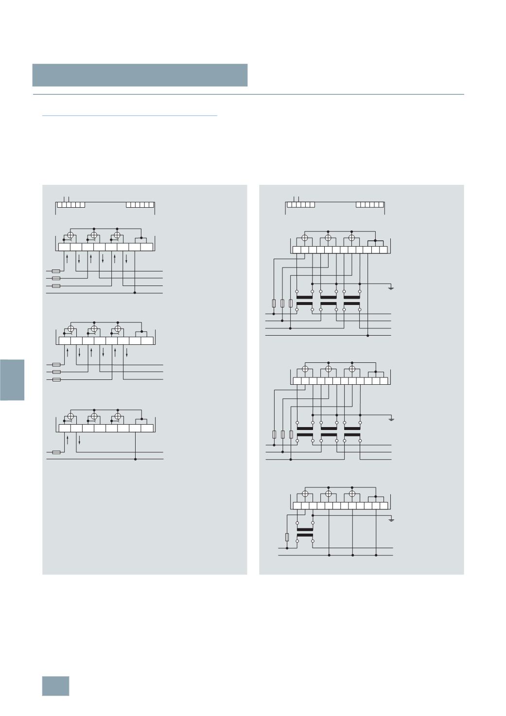
Schematics
Instructions for the connection of transformer counters
In the case of cross-section reduction, a short-circuit resistant
cable is required for the power supply of terminal 2, depending
on the fusing for phases L1, L2, L3. A fuse of 6 A is recommended
for the line protection.
Current transformers must not be operated with open terminals
as this can result in dangerously high voltages, which may result
in personal injuries and property damage. It can also lead to a
thermal overload of the transformers.
2 3
I2_11424a
L1
L2
L3
L1 L1 L2 L2 L3 L3 N N
63
A
63
A
63
A
L1
N
L1 L1 L2 L2 L3 L3 N N
63
A
L1
L2
L3
L1 L1 L2 L2 L3 L3 N N
N
63
A
63
A
7
KT1 300
L N
63
A
400
V AC
Direct connection 63 A, 3-wire circuit
230
V AC
Direct connection 63 A, single-phase
230/400
V AC
Direct connection 63 A, 4-wire circuit
230
V AC
7
KT1 301
L N
7
KT1 302
L1
L2
L3
6
A
I2_11425b
2 3
k1 L1 l1 k2 L2 l2 k3 L3 l3 N N N
K
l
L
k
6
A
L1
N
k1 L1 l1 k2 L2 l2 k3 L3 l3 N N N
K
l
L
k
K
l
L
k
K
l
L
k
6
A 6 A 6 A
L1
L2
L3
N
k1 L1 l1 k2 L2 l2 k3 L3 l3 N N N
K
l
L
k
K
l
L
k
K
l
L
k
6
A 6 A
230
V AC
400
V AC
Current transformer connection, 3-wire circuit
230
V AC
Current transformer connection, single-phase
230/400
V AC
Current transformer connection, 4-wire circuit
© Siemens AG 2008