


 378 / 582

BETA Switching
Switching Devices
Circuit protection
8/30
Siemens ET B1 · 10/2008
8
*
You can order this quantity or a multiple thereof.
■
Overview
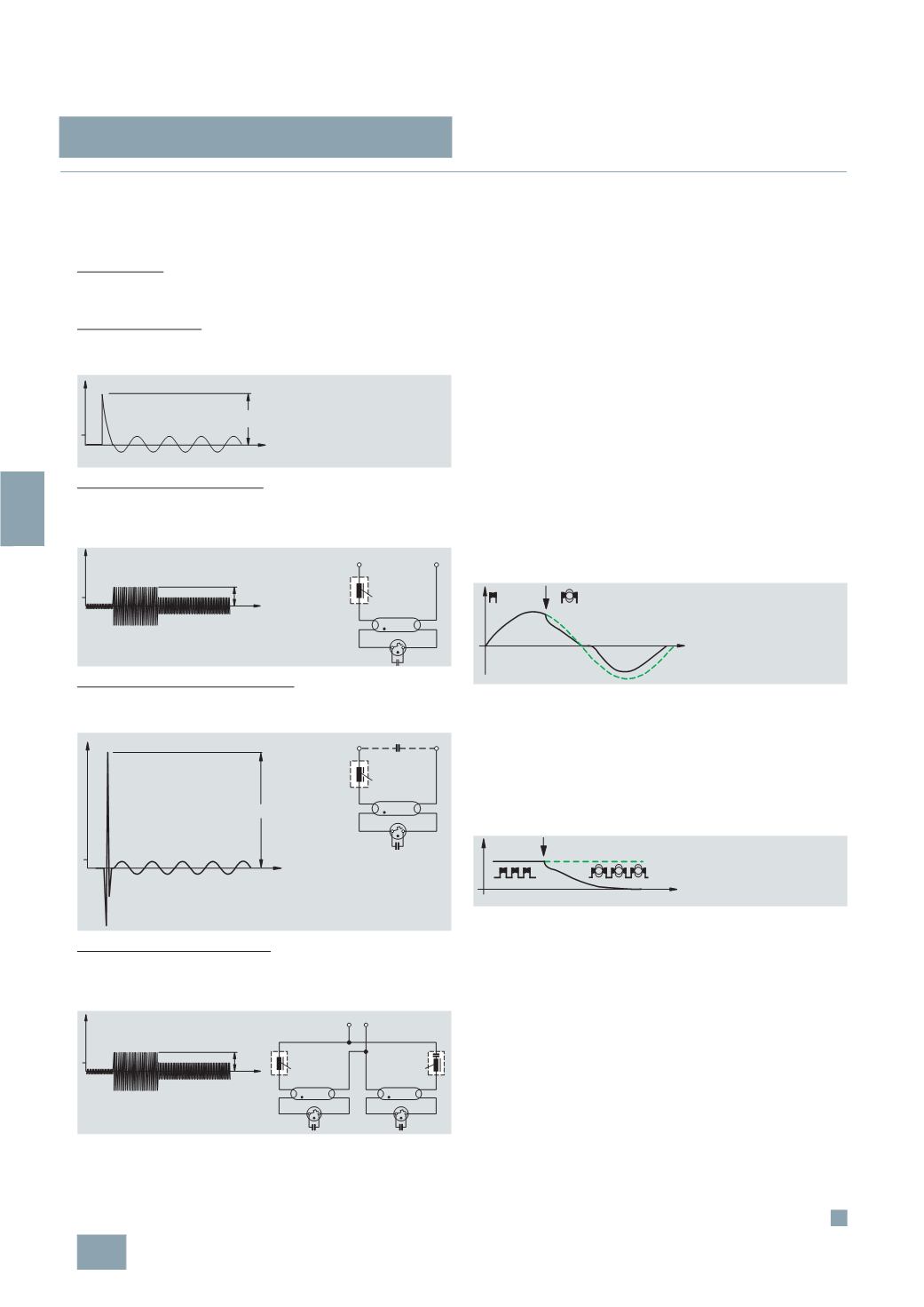
Connecting loads
The increased starting currents of different loads and thus the
risk of contacts welding is often underestimated.
Resistive load:
The resistive load, e.g. electrical heating, does not increase the
starting current.
Incandescent lamps:
The cold coiled filament in incandescent lamps or halogen
lamps causes a 6 to 10-fold starting current for approx. 10 ms.
Uncorrected fluorescent lamps:
When switched on over several periods, the heating current of
the coiled filament and the operational current produce a 2 to
2.5-
fold inductive current.
Parallel-corrected fluorescent lamps:
When switched on, the capacitor causes an extreme, up to 13-fold,
current for approx. 10 ms.
Fluorescent lamps in Duo circuit:
The series capacitor effects a correction. In spite of this, an
increased starting current is produced over several periods, just
as for uncorrected fluorescent lamps.
Selecting contacts for lighting installations
A wide range of different contacts are used for modular installation
devices:
•
Contacts with > 3 mm contact gap, as for Insta contactors,
AC technology
•
Switching relay contacts with m contacts (contact gap
> 1.2 mm but < 3 mm)
•
Manually operated contacts with > 3 mm contact gap, as for
5
TE8 switches
•
Relay contacts with contacts (contact gap > 0.5 mm), like
those used on the printed boards of electronic devices.
The selection tables in the technical specifications help you to
find the correct switching device for the different lighting
installations.
Disconnecting loads
If a contact with current flowing through it opens, this always
ignites an electric arc from around 24 to 30 V. This electric arc
depends on the voltage, the length of the isolating distance,
contact speed, actuating angle and current intensity. The
principle of the so-called zero cutoff is that after no more than
1½
half-waves, the electric arc is quenched in the current zero.
There are no further quenching aids or current limiters, as is the
case with the miniature circuit breakers.
Disconnecting direct currents
When switching direct voltages, there is no zero-crossing of the
current to quench the electric arc. In order to still be able to
switch appreciable currents, contacts are connected in series to
increase the isolating distance.
Some switching devices are provided with planning data for
switching direct currents. Compliance with these planning data
is essential. If the data values are exceeded the electric arc is
not reliably quenched and there is a risk of fire.
Safe isolation
When operating 230 V and safety extra-low voltage SELV
–
voltage of bell transformers or transformers for permanent load
–
on a device, it is essential to ensure "safe isolation". This
requires at least 8 mm creepage distances and clearances and
a voltage endurance greater than 4 kV. If these conditions –
8
mm or 4 kV – are not fulfilled, the term "electrical isolation" as
"
not SELV" is used instead of the term "safe isolation".
8 ...10
t
I2_07254a
1
V
D
L
St
L1
N
I2_07256a
t
1
I2_07255a
2 ... 2.5
t
1
I2_07257a
approx.13
V
D
L
St
L1
N
I2_07258a
t
1
I2_07255a
2 ... 2.5
V
D
K
1
L
St
L1 N
I2_07259a
V
D
L
St
© Siemens AG 2008