


 337 / 582

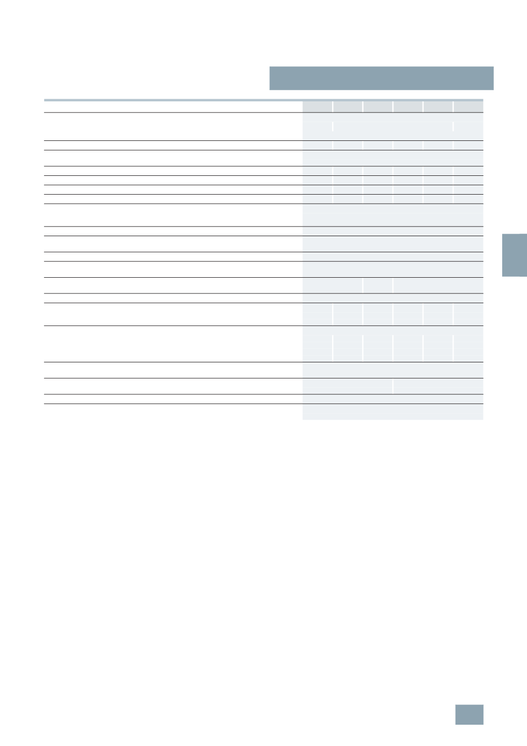
BETA Switching
Switches and Light Indicators
5
TE8 ON/OFF switches
7/17
Siemens ET B1 · 10/2008
7
*
You can order this quantity or a multiple thereof.
5
TE8 3 5TE8 4 5TE8 5 5TE8 6 5TE8 7 5TE8 8
Standards
IEC/EN 60947-3 (VDE 0660-107)
--
IEC/EN 60669-1 (VDE 0632-1)
--
Approved acc. to
EN 60669-1
Rated operational current
I
e
Per conducting path
A
32
40
63
80
100
125
Rated operational voltage U
e
1-
pole
V AC 230
Multipole
V AC 400
Rated power dissipation P
v
Per pole, max.
VA
0.7
0.9
2.2
3.5
5.5
8.6
Thermal rated current
I
th
A
32
40
63
80
100
125
Rated breaking capacity
At p.f. = 0.65
A
96
120
196
240
300
375
Rated making capacity
At p.f. = 0.65
A
96
120
196
240
300
375
Short-circuit strength
In conjunction with fuse of the same
rated operational current
EN 60269 gL/gG
kA
10
Rated impulse withstand voltage U
imp
kV
> 5
Clearances
Open contacts
mm > 7
Between the poles
mm > 7
Creepage distances
mm > 7
Mechanical service life
Switching
cycles
20000
Electrical service life
Switching
cycles
10000
5000 1000
Minimum contact load
V; mA 24; 300
Rated power
1-
pole
kW 5
6.5
10
13
16
16
Switching of resistive loads
2-
pole
kW 9
11
18
22
28
28
including moderate overload AC-21
3-/4-
pole
kW 15
15
30
39
48
48
Rated short-time currents
2)
Per conducting path at p.f. = 0.7
Up to 0.2 s
A
760
950
1500 2700 3400 3400
Up to 0.5 s
A
500
630
1000 1650 2100 2100
(
The corresponding rated surge current can be
established by multiplying by factor 1.5.)
Up to 1 s
A
400
500
800 1350 1700 1700
Up to 3 s
A
280
350
560
800 1000 1000
Terminals
± screw (Pozidriv)
2
Max. tightening torque
Nm 3.5
Conductor cross-sections
Rigid
mm
2
1 ... 35
2.5 ... 50
Flexible, with end sleeve mm
2
1 ... 35
2.5 ... 50
Permissible ambient temperature
°C
-5 ...
+40
Resistance to climate
At 95 % relative humidity
Acc. to DIN 50015
°C
45
© Siemens AG 2008