


 164 / 582

BETA Protecting
Low-Voltage Fuse Systems
DIAZED fuse systems
3/14
Siemens ET B1 · 10/2008
3
*
You can order this quantity or a multiple thereof.
■
Overview
The DIAZED fuse system is one of the oldest fuse systems in the
world. It was developed by Siemens as far back as 1906. It is still the
standard fuse system in many countries to this day. It is particularly
widely used in the harsh environments of industrial applications.
The series is available with rated voltages from 500 to 750 V.
All DIAZED bases must be fed from the bottom to ensure an insulated
threaded ring when the fuse link is being removed. Reliable contact
of the fuse links is only ensured when used together with DIAZED
screw adapters.
The terminals of the DIAZED bases are available in different versions
and designs to support the various installation methods.
A key feature is the high-performing EZR bus-mounting system for screw
fixing. The busbars, which are particularly suited for bus-mounting
bases, have a load capacity of up to 150 A with lateral infeed.
DIAZED stands for
"
Dia
metral gestuftes
z
weiteiliges Sicherungssystem
mit
Ed
isongewinde" (diametral two-step fuse system with Edison
screw).
■
Benefits
■
Technical specifications
DIAZED fuse systems area a result of the well-designed modular
system, the components can be combined in any way to meet
the various requirements and to facilitate different installation
methods.
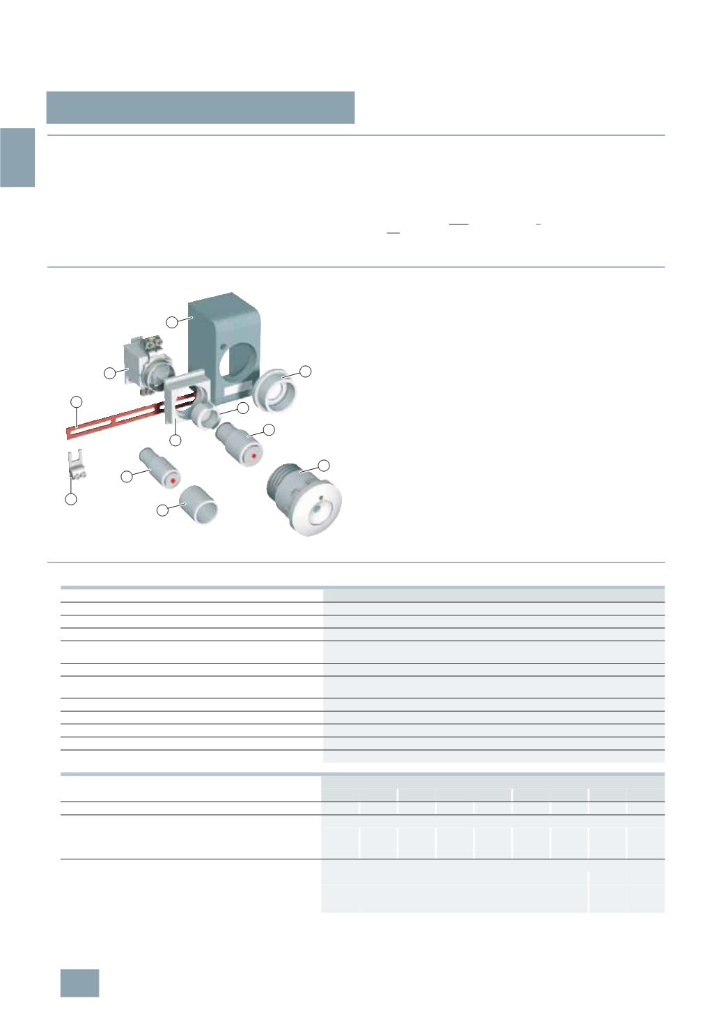
$
DIAZED base
%
DIAZED cover
&
DIAZED cover ring
(
DIAZED cap
)
DIAZED fuse link, DII
*
DIAZED fuse link, NDz
+
DIAZED screw adapter
,
DIAZED adapter sleeve
-
DIAZED screw cap
.
Busbar, oblong hole, single-phase
/
Terminal, fork-type terminal, non-insulated
5
SA, 5SB, 5SC, 5SD
Standards
IEC 60269-3; DIN VDE 0635; DIN VDE 0636-3; CEE 16
Operational class
Acc. to IEC 60269; DIN VDE 0636
gG
Characteristic
Acc. to DIN VDE 0635
Slow and quick
Rated voltage U
n
V AC 500, 690, 750
V DC 500, 600, 750
Rated current
I
n
A
2 ... 100
Rated breaking capacity
kA AC 50, 40 at E16
kA DC 8, 1.6 at E16
Mounting position
Any, but preferably vertical
Non-interchangeability
Using screw adapter or adapter sleeves
Degree of protection
Acc. to IEC 60529
IP20, with connected conductors
Resistance to climate
°C
Up to 45, at 95 % rel. humidity
Ambient temperature
°C
-5 ...
+40, humidity 90 % at 20
Terminal type
B
K
NO
R
Size
DII
DIII
NDz
DII
DIII
DIII
DIV DII
DIII
Conductor cross-sections
•
Rigid, min.
mm
2
1.5
2.5
1.0
1.5
2.5
2.5
10
1.5
1.5
•
Rigid, max.
mm
2
10
25
6
10
25
25
50
35
35
•
Flexible, with end sleeve
mm
2
10
25
6
10
25
25
50
35
35
Tightening torque
•
Screw M4
Nm 1.2
--
•
Screw M5
Nm 2.0
--
•
Screw M6
Nm 2.5
4
•
Screw M8
Nm 3.5
--
7
9
5
3
6
8
11
10
2
1
4
I2_16013
© Siemens AG 2008