


 244 / 543

17/148 Circuit-breakers, switch-disconnectors
Cable protection, back-up protection
2010 CA08103002Z-EN
www.eaton.comCableprotection,back-upprotection
Protection of PVC insulated cables against thermal overload due to short-circuits
According to VDE 0100 Part 430 Wiring Regulations,
cables and conductors must be protected from
overload and short-circuits. In circuit-breakers
NZM, overload protection is implemented through
the adjustable, current-dependently delayed over-
load release.
Short-circuit protection is provided by adjustable
instantaneous releases, which open the main
contacts in less than 25 ms. The short-circuit total
opening time restricts the temperature rise of the
cable to a minimum.
The tables indicate the minimum conductor cross-
section reliably protected by circuit-breakers
during a short-circuit.
(Operating voltage U
N
= 415 V)
Minimum protected
cross-section mm
2
copper
NZM...1(-4)-...20
6
NZM...1(-4)-...25 – 160
10
NZM...2(-4)-...20 – 300
10
NZM...3(-4)-...250 – 630
16
NZM...4(-4)-...630 – 1600
95
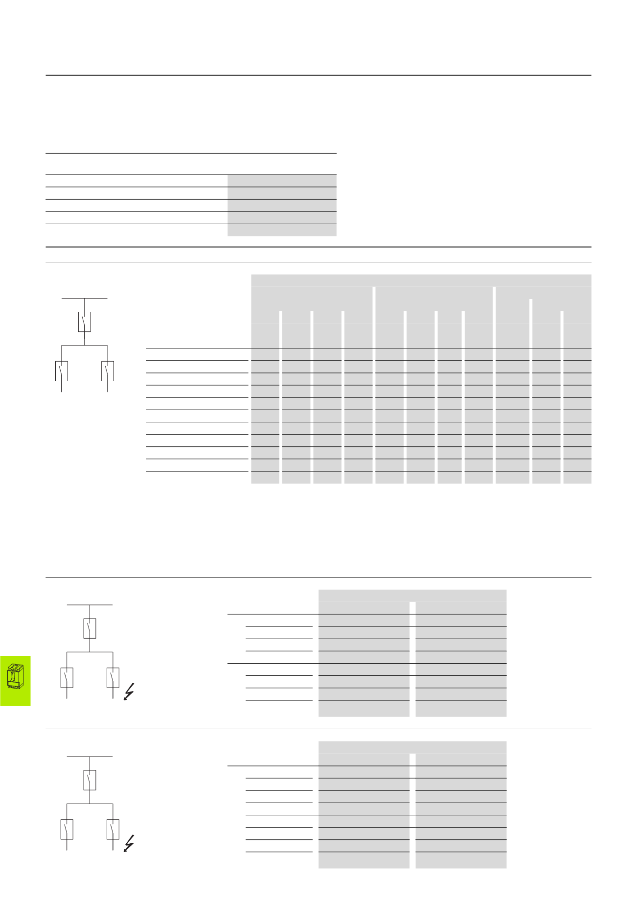
Backup protection
between incoming circuit-breaker NZM(N)(H) and outgoing circuit-breaker NZMB(N)(H)
Incoming circuit-breaker ①
NZM1
NZM2
NZM3
I
n
Up to 160 A
Up to 250 A
Up to500A Up to 630 A
I
cu
(415 V) 25 kA 36 kA 50 kA 100 kA 25 kA 36 kA 50 kA 150 kA 36 kA 50 kA 150 kA
Outgoing circuit-breaker ②
I
cu
(415 V) I
n
NZMB1 25 kA Up to 160 A 25
36
50
100
25
36
50
100
36
50
100
NZMC1 36 kA Up to 160 A –
36
50
100
–
36
50
100
36
50
100
NZMN1 50 kA Up to 160 A –
–
50
100
–
–
50
100
–
50
100
NZMH1 100 kA Up to 160 A –
–
–
100
–
–
–
100
–
–
100
NZMB2 25 kA Up to 300 A 25
36
50
100
25
36
50
150
36
50
150
NZMC2 36 kA Up to 300 A –
36
50
100
–
36
50
150
36
50
150
NZMN2 50 kA Up to 300 A –
–
50
100
–
–
50
150
–
50
150
NZMH2 150 kA Up to 300 A –
–
–
–
–
–
–
150
–
–
150
NZMC3 36 kA Up to 500 A –
–
–
–
–
–
–
–
–
50
150
NZMN3 50 kA Up to 630 A –
–
–
–
–
–
–
–
–
50
150
NZMH3 150 kA Up to 630 A –
–
–
–
–
–
–
–
–
–
150
Where the prospective fault current at the mounting
location of circuit-breakers is very high current-
limiting circuit-breakers NZMN(H) are normally used.
A cost-effective alternative if the fault level is too high
for circuit-breakers NZMB(C)(N) is to fit a current-
limiting circuit-breaker NZMN(H) upstream of an
arrangement of standard circuit-breakers
NZMB(C)(N).
The table shows which current-limiting circuit-
breakers NZMN(H) provide reliable protection at
network locations with high short-circuit ratings in
combination with NZMB(C)(N).
The selectivity limit is determined by the response
current of the non-delayed short-circuit release in
the upstream incoming circuit-breaker. In many
applications this is sufficient.
between incoming circuit-breaker NZM...1-A... and outgoing circuit-breaker FAZ-B(C)/PLSM-B(C)...
Outgoing circuit-breaker Incoming circuit-breaker
NZMB1-A...
NZMC(N)(H)1-A...
FAZ-B(C)...
0.5 – 16
25 kA
30 kA
20 – 40
20 kA
20 kA
50, 63
15 kA
15 kA
PLSM-B(C)...(/...)
0.5 – 16
25 kA
30 kA
20 – 40
20 kA
20 kA
50, 63
15 kA
15 kA
between incoming circuit-breaker NZM...2-A... and outgoing circuit-breaker FAZ-B(C)/PLSM-B(C)...
Outgoing circuit-breaker Incoming circuit-breaker
NZMB2-A...
NZMN(H)2-A...
FAZ-B(C)...
0.5 – 10
25 kA
50 kA
13 – 32
25 kA
30 kA
40 – 63
20 kA
20 kA
PLSM-B(C)...(/...)
0.5 – 10
25 kA
50 kA
13 – 32
25 kA
30 kA
40 – 63
20 kA
20 kA
b
I
cc
a
NZM...
NZM...
I
cc
FAZ...
PLSM...
NZM...
I
cc
FAZ...
PLSM...
NZM...
NZM1, NZM2, NZM3