


 256 / 336

2010 CA08103002Z-EN
www.eaton.comCam switches, switch-disconnectors
Switch-disconnectors – safety switches
Without emergency switching off/
emergency stop function
2)
Surface mounting
IP65
Part no.
Article no.
Price
See price
list
Std. pack
Notes
P1-25/I2-SI-SW
3)
207309
1 Off
P1-32/I2-SI-SW
3)
207330
P3-63/I4-SI-SW
3)
207362
P3-100/I5-SI-SW
3)
207387
P1-25/I2-SI/HI11-SW
3)
207311
P1-32/I2-SI/HI11-SW
3)
207332
P3-63/I4-SI/HI11-SW
3)
207364
P3-100/I5-SI/HI11-SW
3)
207389
P1-25/I2-SI/N-SW
3)
207313
P1-32/I2-SI/N-SW
3)
207334
P3-63/I4-SI/N-SW
3)
207366
P3-100/I5-SI/N-SW
3)
207391
T5B-3-8342/I4-SI-SW
4)
207251
T5-3-8342/I5-SI-SW
4)
207448
T5B-4-15682/I4-SI-SW
4)
207255
T5-4-15682/I5-SI-SW
4)
207286
T5B-4-8903/I4-SI-SW
4)
207259
T5-4-8903/I5-SI-SW
4)
207290
Engineering
Maintenance, repair and safety switches all have
the same electrical function. They are designed to
safely isolate electrical installations (loads) from
mains power during maintenance and repair work
and to ensure that a hazard does not arise which
endangers personnel, machinery and production
materials.
A safety switch is an additional enclosed main
switch = isolator dedicated to an individual
electrical load and mounted in the immediate
vicinity of the motor or the electrical load.
This is particularly important if there is any danger
of the main switch being inadvertently operated.
Application
By using his padlock (up to 3), each fitter/electrician
involved can protect themselves by preventing
unauthorized personnel from switching the unit on.
Maintenance/manual override switches are simply
additional enclosed main switches with a
padlocking feature.
Enclosed main switch with padlocking facility
Features
• Safety switches are always housed in insulated
enclosures and have an inscription saying
"Safety Switch" on a bright orange label.
• Switches to be used for emergency stop switch-
ing have a red handle and yellow locking collar in
accordance with STOP category O (as per
IEC/EN 60204/VDE 0113).
• If the switch is not approved for emergency stop
switching, both parts will be black ("SW" part no.
suffix).
• The cover and handle are interlocked by fitting a
padlock.
Selection
The switches must be selected according to the following per-
formance specifications:
1) According to motor switching capacity, when the switch is
fitted in such a way that the operator may use it for operational
ON and OFF switching.
2) The rating data always applies to 3 poles. When the motor
rating is divided between 6 poles, such as for star-delta
switching, a 6 pole switch can be used to control 1.73 times
the rated power.
3) If the switch has a load-shedding Contact (LA), you can
select the appropriate switch according to the uninterrupted
current. The load-shedding contact is an auxiliary contact,
which is closed in the ON position and opens early when
switching off, so that a contactor located in the circuit takes
over the switching duty and the maintenance/safety switch
operates at zero load. When switching on, the load-shedding
contact closes later than or at the same time as the main con-
tacts. With P and T switches this is the N/O auxiliary contact.
4)The "ON" position can be locked with a padlock (by altering
the handle).
This is not permissible for switches with a red/yellow handle.
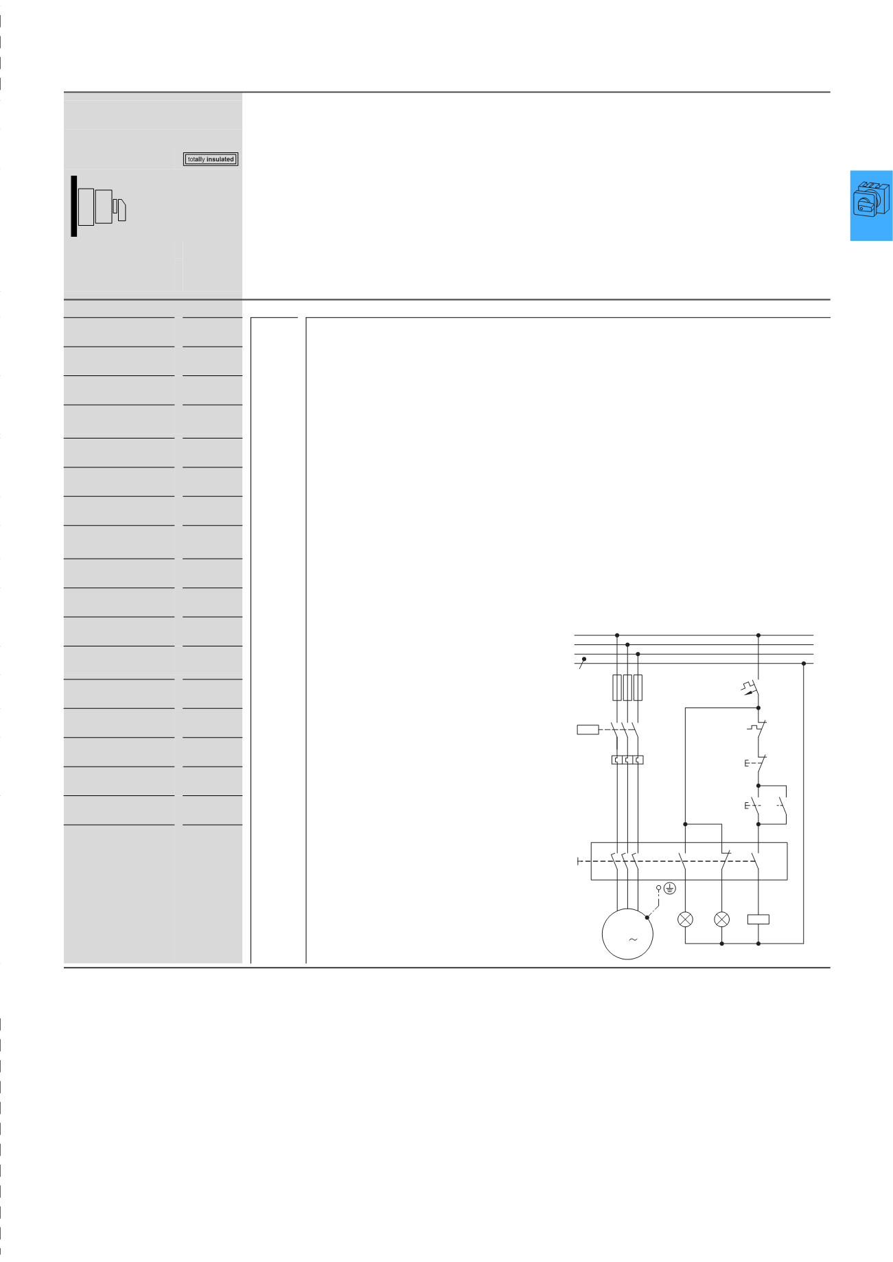
Safety switch with load shedding and signaling
Q11
L2
N
L3
L1
F1
Q11
2
1
4
3
6
5
F2
1 3 5
2 4 6
M
3
7
9
11
8
10
12
Q1
U V W
A2
Q11
A1
P1
P2
F0
95
96
21
22
F2
O
13
14
I
13
14
FAZ-
B4/1-HS
4/31
T, P
HPL04031EN