


 13 / 16

WARWI CK
GENE RA L NOT E S
12
STANDARDS
Manufactured to comply with the
requirements of BS4678: Part 4
(1982)
and BSEN 50085-1 (1999).
The Electrium group of companies
is registered for assessed capability
to ISO 9002 Part 1.
The WARWICK range complies with
all requirements of the 16th Edition
of the IEE Regulations.
MANUFACTURE
All trunking components are
manufactured from PVCu material.
Base sections, covers and bus-bar
base sections are extruded.
Bends, corners, stop ends, joint
covers and accessory boxes are
formed by injection moulding.
Flat angles and tees are factory pre-
fabricated from standard profiles.
STRENGTH
High impact resistant. The material
is formulated to comply with
BS4678 Part4 (1982). Temperature
classification -5 to +60°C for
permanent application range.
FINISH
Manufactured in White Semi-glass
finish.
FIRE RESISTANCE
The PVCu used in WARWICK
trunking is non-propagating and
complies with the requirements of
BS476 parts 5 & 7 and BS4678
Part 4.
DEGREE OF PROTECTION
IP4X
THERMAL PROPERTIES
Water Absorbtion – Negligible
Mineral Acids
–
Excellent
Detergents
–
Excellent
Note:
Some solvents such as Ketones,
Aromatics and Hydrocarbons should
not be used on PVC trunking
CABLE CAPACITIES
The following table is from the 16th
edition of the IEE Wiring Regulations:
Guidance Note 1: Selection and
Erection of equipment.
The table refers to single core PVC
Insulating cables only.
TABLE A5
CABLE FACTORS FOR TRUNKING
Type of
Conductor
Term
Conductor Cross - Sect.
Area
Solid
1.5
7.1
2.5
10.2
1.5
8.1
2.5
11.4
Standard
4.0
15.2
6.0
22.9
10.0
36.3
This Appendix is a method which
can be used to determine the size
of trunking necessary to
accommodate cables of the same
size, or different sizes.
The number of cables drawn into
or laid in an enclosure of a wiring
system shall be such that no damage
is caused to the cables or to the
enclosure during their installation.
For trunking each size of cable has
been allocated a term, as has each
trunking. To ascertain the size of
trunking required, add together all
the cable terms and compare against
the trunking terms given in the
following figures.
Note:
For power cables a space factor of
45%
must apply, therefore, the
following terms represent this in the
internal area figures.
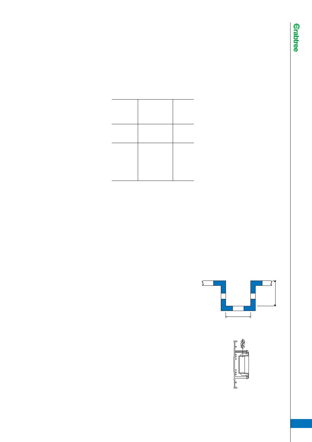
Angled Top/Bottom section:-
Area 1176mm Term Value 532
Central section:-
Area 3483mm Term Value 1576
Square Top/Bottom section:-
Area 1507mm Term Value 682
Extended Bottom section:-
Area 3499mm Term Value 1583
INSTALLATION
RECOMMENDATIONS
1)
The base section and extension
base (if used) should be plug and
screw fixed to the wall ensuring
washers are used behind the
screw head for a more secure fix.
2)
All joints should have a 5mm gap
to allow for expansion and base
section corners should be mitred.
The cutting of the base sections
is not critical as the manufactured
fittings cover the joints and
overlap the trunking lids.
3)
For cutting it is recommended
that a fine tooth tenon or
hacksaw is used. Use a sharp
knife or file for trimming.
4)
Should screening be required
this can now be inserted into
the relevant compartment.
5)
Socket and data boxes can be
positioned and wiring can begin.
6)
On completion of all wiring, the
covers, joint covers etc can be
inserted.
7)
Finally, all power/data/telephone
accessories can be wired and
fixed.
The Earth Loop Impedance Test can
now be carried out.
INSTALLATION TIPS
Installation around columns.
Accessory Boxes
All boxes are on the same plain.
Therefore, holes should be drilled
from top or bottom to accommodate
data and telephone cabling.
76
mm
Min
138
mm
Min
Drill hole of
suitable size