


 12 / 16

WARWI CK
BUS - BAR T ECHN I CA L DATA
11
ELECTRICAL DATA
The Bus-Bar is rated at 63A, 250V
AC., 50/60Hz single phase.
Average ambient temperature 35°C
over 24 hour period.
SHORT CIRCUIT RATING
Short circuit protection provided by
fuse-links BS88 and BS1361, 63A
maximum.
Prospective current
16.5
kA
Mechanical withstand 10kA peak
Thermal withstand 1.2kA for
0.4
seconds.
CABLE CAPACITY OF TERMINALS
Mains Connector Block 25mm
2
13
A accessories
10
mm
2
VOLT DROP
Bus-Bar (line & neutral) 3.3mV/A/m
Track Connector
0.44
mV/A
Supply Connector
0.22
mV/A
EARTH FAULT LOOP IMPEDANCE
The IEE wiring regulations require
accurate determination of the
total earth loop impedance, which
must be low enough to ensure
that the protective device will
operate within the specified time,
which for circuits incorporating
socket outlets is 0.4 seconds. The
values for the WARWICK Bus-Bar
system for calculating the earth fault
loop impedance are as follows.
Phase Bus-Bar:-
1.6
m
Ω
/
m of conductor
Earth Bus-Bar:-
1-6
m
Ω
/
m of conductor
Track Connector 0.4m
Ω
typical
STANDARDS
Trunking to:
BS4678 Part 4
Bus-Bar trunking to
BSEN60439-2: 1993
Accessories to: BS1363 (1984)
BS 3676 :1: (1989)
BS 5733 (1979)
ASSEMBLY/INSTALLATION
The WARWICK Bus-Bar system has
been designed so that no cutting
of the Bus-Bar section is required,
various lengths from 3 metres to 0.5
metres being available.
Plan the
proposed runs accordingly.
For installations requiring Bus-Bar,
we strongly recommend the order
is handled by the PROJECT SALES
TEAM who offer a free installation
design service.
1)
Fix the base section to the wall,
ensuring that the Crabtree/
Britmac name is at the TOP
(
as per the standard sections).
2)
When the straight trunking
lengths have all been fixed and
secured, the Bus-Bar sections can
be snapped into place.
3)
All the Bus-Bar couplers, corner
assemblies and stop ends can
now be fitted.
4)
Once the whole Bus-Bar section
has been connected together,
positioning of all plug-in power
back boxes can be snapped into
the Bus-Bar.
5)
At this point the Bus-Bar cover
can be installed, ensuring the
covers are fixed tight to the boxes
with no gaps showing.
6)
Back boxes for data/telephones
can now be positioned and
wired.
7)
Should metal screening be
required, this should be inserted
in the top and bottom sections of
the trunking prior to wiring of the
data and telephone systems.
8)
All internal wiring and installation
should be checked before any
external covers are fixed.
9)
The snap-on external covers can
now be installed.
10)
Finally, the wiring of the power
outlets and the data and
telephone accessories should
complete the installation.
GENERAL INFORMATION
Expansion/Contraction – Allowance
should be made for thermal
movement. A 5mm gap between
each length of the trunking base is
recommended. Couplers on the
bases are not required.
Planning - if the trunking is to be
utilised as a skirting system,
sufficient clearance for lids and
carpeting should be catered for.
Internal Bus-Bar Cover – Once the
system has been made live, the
internal cover must not be removed.
Data/Telephone boxes can be
installed without removing the
Bus-Bar cover.
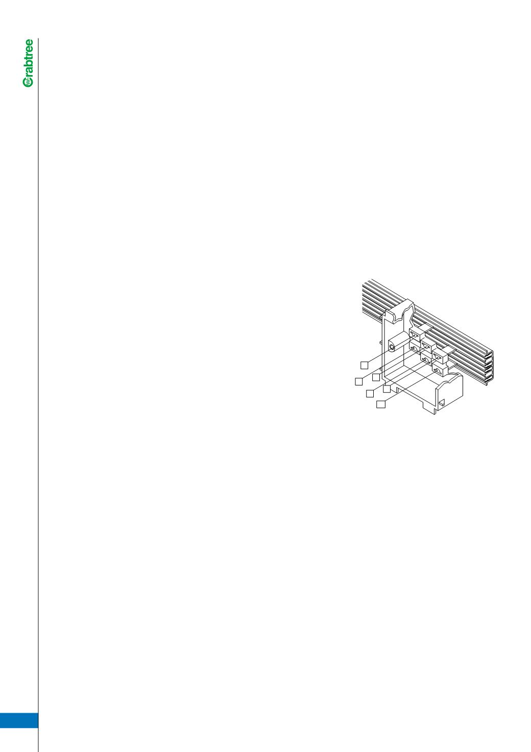
BUS-BAR CONFIGURATION
If clean earth bar is not required, no
connection on bottom termination is
necessary.
SITEWORK
Perimeter systems are designed in
accordance with I.E.E. regulations
and allow installers to comply with
these regulations. The above
installation notes are for guidance
purposes and to assist good practice
and workmanship. It is the duty of
the installer to ensure that I.E.E.
regulations are being met with
regard to the finished installation.
NOTE: Although every effort has been made to ensure accuracy in the compilation of the technical detail within this publication, specifications and performance data
are constantly changing. Latest details can be obtained from Crabtree.
L
N
E
X
CE
X