


 65 / 81

65
Lifeline Range RCDs – Technical
Data
OPERATION
The RCD employs the current balance principle which involves the supply
conductors to the load (phase and neutral) being wound onto a common
transformer core to form the primary windings. Under healthy circuit
conditions, the current in the phase conductor is equal to the current in the
neutral, and the vector sum of the current is zero.
In the event of an earth fault, an amount of current will flow to earth,
creating an out of balance situation in the transformer assembly.
This out of balance is detected by the secondary winding of the transformer
and at a pre-determined level of out of balance will activate the trip
mechanism.
Single phase and neutral or three phase and neutral units (suitable for 3
or 4 wire systems) are available, the latter being suitable for balanced
or unbalanced 3 phase loads.
The RCD trip mechanism will operate at a residual current of between 50–
100% of its rating tripping current (sensitivity).
TRANSIENT EARTH LEAKAGE CURRENTS
AllWylex residual current devices incorporate a high level of immunity to
tripping when subjected to transient earth leakage currents.
Such transients can occur when there is a significant level of capacitance to
earth as can result from cable capacitance (particularly MICC) or RF filter
networks.Wylex RCDs are therefore less susceptible to nuisance tripping
due to transient earth leakage currents.
RESIDUAL TRIPPING CURRENTS
10mA-
Used in special applications where additional protection against contact is
essential due to the nature of the installation.
30mA-
Tripping current designated by the IEEWiring Regulations to provide
additional protection.
100mA-
Suitable for use where protection is provided to guard against firehazard,
etc, rather than to provide additional protection to personnel, and where
the earthing requirements need supplementing by RCD protection.
100mA time delay-
Suitable for use when total RCD protection is required to supplement the
system earthing and where local 30mA RCDs are used to give additional
protection.The time delay RCD will discriminate with the 30mA RCD.
300mA-
For use in large installations where plant and equipment protection are the
main considerations and high levels of earth leakage are experienced.
If using RCDs in series, discrimination can only be achieved by using Type S
devices in series with Types A or AC. See chart below.
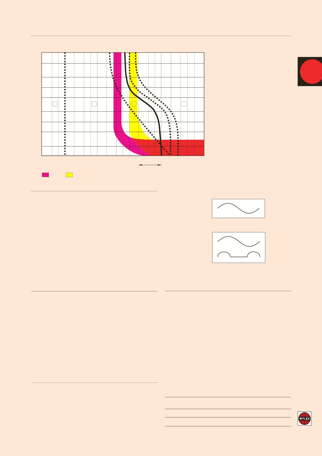
IEC PUBLICATION (60479) CURVESWITHWYLEX RCD CHARACTERISTICS SUPERIMPOSED
TIME/CURRENT ZONES OF EFFECT OF AC CURRENT (15–100Hz) ON PERSONS
FAULT CURRENT SENSITIVITY
As the equipment is fed from the mains electrical supply, in the event of
an earth fault the presence of semi-conductors may result in the normal
ac waveform being replaced by a non-sinusoidal fault current. In some
cases the waveform may be rectified or chopped.These waveforms are
said to contain a pulsating dc component which can either partially
desensitise or totally disable a standard Type AC RCD.
International standards IEC 61008 (RCCBs) and IEC 61009 (RCBOs)
divide RCDs into two performance classes:
Type AC
RCDs for which tripping is ensured for residual sinusoidal alternating
currents, whether suddenly applied or slowly arising.
Type A
RCDs for which tripping is ensured for residual sinusoidal alternating
currents and residual pulsating direct currents, whether suddenly
applied or slowly arising.
To ensure the correct level of protection, check for the following
symbols:
TYPEAC
normal ac sensitivity
TYPEA
pulsating dc sensitivity
Wylex RCDs are available as both Type AC and Type A devices.
Technical details for Type B RCDs available on request.
10,000
5,000
2000
1000
500
200
100
50
20
10
0.1 0.2 0.3 0.5 1 2 3 5 10 20 30 50 100 200 300 500 1,000 2,000
10,000
mA
5,000
3,000
Body current in milliamperes (RMS)
100mA
30mA
Typical current
Limits due to body resistance
at 230V
1
2
3
4
a
b
c1 c2 c3
IEC 60479
Time in milliseconds
Zone Physiological effects
1
Usually no reaction effects (no danger).
2
Usually no harmful physiological effects
(usually no effects).
3
Usually no organic damage to be expected.
Likelihood of muscular contraction and
difficulty of breathing, reversible
disturbances of formation and conduction
of impulses in the heart, and transient
cardiac arrest without ventricular fibrillation
increases with current magnitude and time.
4
In addition to the effects of zone 3,
probability of ventricular fibrillation
increased up to 5% (Curve C2), up to 50%
(Curve C3) and above 50% beyond Curve
C3. Increasing with magnitude and time,
pathyphysiological effects such as cardiac
arrest, breathing arrest and heavy burns
may occur.
BSEN61008-1:1995 RCBOs BSEN61009-1:1995
l
Rated Residual Current (
I
n) Tripping
Type of RCD RCD toTrip between times
50%-100%
I
n 1x
I
n 2x
I
n 5x
I
n 500Amps Scope
Standard
AnyValue,eg 10,30,100mA 300ms 150ms 40ms 40ms Maximum-Trip
A &AC
Time Delay
Greater than 30mA,eg 100mA
500ms 200ms 150ms 150ms Maximum-Trip
(S) 130ms 60ms 50ms 40ms Minimum-NonTrip