


 3 / 4
3 / 4

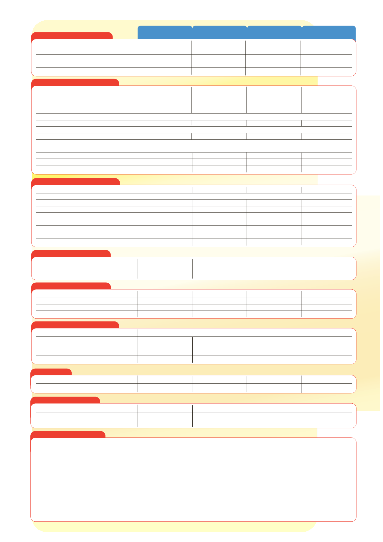
Power Supply Specification
fp technical specifications
p
s
i
EFP1
FP2, FP2E
FP4, FP6, FP8E
FP8, FP10, FP12, FP14
Detector Circuit Specification
Sounder Circuit Specification
Battery Stand-By Times
EFP1
FP2
FP4E
FP4
FP6
FP8E
FP8
FP10 FP12 FP14
Quiescent current
25mA 40mA 50mA 50mA 60mA 70mA 70mA 80mA 90m 100mA
Max. load current
0.4A
0.8A 0.8A 1.4A 1.4A 1.4A 3.0A 3.0A 3.0A 3.0A
Stand-by time in hours using 1.2 Ahr batteries
48
-
-
-
-
-
-
-
-
-
Stand-by time in hours using 2.0 Ahr batteries
80
40
32
26
-
-
-
-
-
-
Stand-by time in hours using 2.6 Ahr batteries
-
55
44
38
32
27
-
-
-
-
Stand-by time in hours using 4.0 Ahr batteries
-
90
72
66
55
47
36
31
28
25
Stand-by time in hours using 6.0 Ahr batteries
-
-
-
106
88
75
64
56
50
45
Stand-by time in hours using 10.0 Ahr batteries
-
-
-
-
-
-
121
106
94
85
The quiescent current
given is for the following conditions - mains supply failed, fault beeper muted, no aux. output connections, detector and
sounder end of line devices fitted, no other loads supplied by the panel.
The battery stand-by times
are guidelines only based on the above
conditions and a full sounder load for 30 minutes. Additional loads that increase the quiescent current in the normal state must be considered
when calculating stand-by time. The fault beeper being active will add 10mA and reduced sounder loads will increase the stand-by time. Batteries
in poor condition greatly reduce stand-by time.
FP range of 1-14 zone conventional
fire alarm control panels
Auxiliary Inputs / Outputs
Fuses
(to IEC - EN60127 Pt2)
Panel Indicators and Controls
Dimensions
Repeater Specification
Mains supply voltage
230V a.c ± 10% 50/60 Hz 230V a.c. ± 10% 50/60 Hz 230V a.c. ± 10% 50/60 Hz 230V a.c. ± 10% 50/60 Hz
Internal power supply
27V d.c. nominal
27V d.c nominal
27V d.c nominal
27V d.c nominal
Total output current limited to
400mA @ 230 V a.c.
800mA @ 230 V a.c.
1.4A @ 230 V a.c.
3A @ 230 V a.c.
Supply and battery charger monitored for failure
Yes
Yes
Yes
Yes
Batteries monitored for disconnection and failure
Yes
Yes
Yes
Yes
Number of circuits
1 (EFP1, non-extendable)
2 (FP2, non-extendable)
4 (FP4, extendable to 6)
8 (FP8, extendable to 14)
4 (FP4E, non-extendable)
6 (FP6, non-extendable)
10 (FP10, extendable to 14)
8 (FP8E, non-extendable) 12 (FP12, extendable to 14)
14 (FP14, non-extendable)
Connector blocks
Heavy duty Niglon-type, largest acceptable conductor size 2.5mm
2
Line monitored for open and short circuit faults
Yes
Yes
Yes
Yes
Line monitored for head out/detector removed faults Yes - if optional BF378 or BF378M End of Line Monitoring unit (not supplied) is fitted in place of end of line resistor
End of line resistor value (supplied)
6800
½
5% Tol. 0.25W
6800
½
5% Tol. 0.25 W
6800
½
5% Tol. 0.25 W
6800
½
5% Tol. 0.25 W
Detector continuity diodes Silicon 1N4001 or Schottky type (required if BF378 or BF378M End of Line Monitoring Unit
is fitted to show head out faults)
Call point resistor value (not supplied)
470 - 680
½
0.5 W
470 - 680
½
0.5 W
470 - 680
½
0.5 W
470 - 680
½
0.5 W
Max. number of detectors per zone
20
(max detector current 2mA)
20
(max detector current 2mA)
20
(max detector current 2mA)
20
(max detector current 2mA)
Max. number of manual call points per zone
No limit
No limit
No limit
No limit
Number of circuits
2
2
2
2
Connector blocks
Heavy duty Niglon-type, largest acceptable conductor size 2.5mm
2
End of line resistor value
6800
½
5% Tol. 0.25 W
6800
½
5% Tol. 0.25 W
6800
½
5% Tol. 0.25 W
6800
½
5% Tol. 0.25 W
Line monitored for open and short circuit faults
Yes
Yes
Yes
Yes
Outputs fused at
400mA
1A
1A
1.6A
Max. total output current to all outputs
400mA
800mA
1.4A
3A
Max. number of bells at 25mA
16
32
56
120
Max. number of sounders at 20mA
20
40
70
150
Volt free relay contacts (active when sounders active)
n/a
Yes, 1A 30V d.c. max
Yes, 1A 30V d.c. max
Yes, 1A 30V d.c. max
Available via optional expansion looms (not supplied)
Class change input,
Class change input, zone 1 & zone 2 fire outputs, fault output and reset output
fire output and fault
via FPX loom. Self-contained fire, fault & sounder delay relay modules
output via EFPX loom
are also available (1 per panel instead of FPX loom)
Mains terminal block
125mA T 20mm
200mA T 20mm
400mA T 20mm
630mA T 20mm
Sounder outputs
400mA F 20mm (F1, F2)
1A F 20mm (F2, F3)
1A F 20mm (F2, F3)
1.6A F 20mm (F2, F3)
Auxiliary output
n/a
1A F 20mm (F4)
1A F 20mm (F4)
1A F 20mm (F4)
Battery fuse
1A F 20mm (F3)
1.6A F 20mm (F1
1.6A F 20mm (F1)
3A F 20mm (F1)
External indicators
Mains On; Zone Fire; Zone Fault; Sounder Fault; Battery/Power Supply Fault
Internal Indicators
O/C Fault; S/C Fault
O/C Fault; S/C fault; Zone Isolated; Engineer Test Selected
External controls (keyswitch operated)
Reset; Silence Alarm/Fault
Reset/ Resound/Test Zone Lamps; Evacuate; Silence Alarm Sounders;
Sounders; Evacuate
Silence Fault Sounders
Internal controls
Revert to short circuit = fire
Revert to short circuit = fire; One man detector test; Zone isolate
Approx. dimensions of enclosure (W x H x D)
271 x 200 x 70mm
322 x 267 x 92mm
405 x 267 x 92mm
521 x 334 x 140mm
Weight (without batteries)
2.3 kg
4.3kg
5.0 kg
9.2 kg
Max. number of repeaters
n/a Three repeaters per main panel. Repeaters are available with 10 or 20 zones.
Repeater wiring
n/a
Five control wires plus one extra wire per zone being repeated;
max cable length 200m