


 4-5 / 7

EP203
Automatic Extinguisher Panel &
EP RANGE
Ancillaries
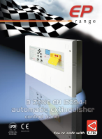
This diagram is provided for illustration purposes only.
Always refer to the relevant instructions before installation.
EP203
EP212
EP210F
EXTINGUISHERRELEASE
PULLDOWNandPUSHBUTTONS
ExtinguisherControlPanel Instructions
Extinguishant
Gas
EXTINGUISHERRELEASE
PULLDOWNandPUSHBUTTONS
EXTINGUISHERRELEASE
PULLDOWNandPUSHBUTTONS
EXTINGUISHERRELEASE
PULLDOWNandPUSHBUTTONS
Remote Status Units
(
Economy Status Units
(Max. 8)
Input Switches
Relay
Board
Detection
Zones
Sounder
Circuits
Fire
Local Fire
1st stage active
2nd stage active
Fault
1st stage
1st stage
2nd stage
1 2 3
Mode/ESU
Hold
Abort
Release
RS485
Gas low pressure switch
Gas flow detection switch
Activate extinguisher solenoid
Extract fan switch
Relay Outputs
Provides reset, mode,
discharged, hold and
abort outputs
AN OVERVIEW OF THE EP203’S INPUTS AND OUTPUTS
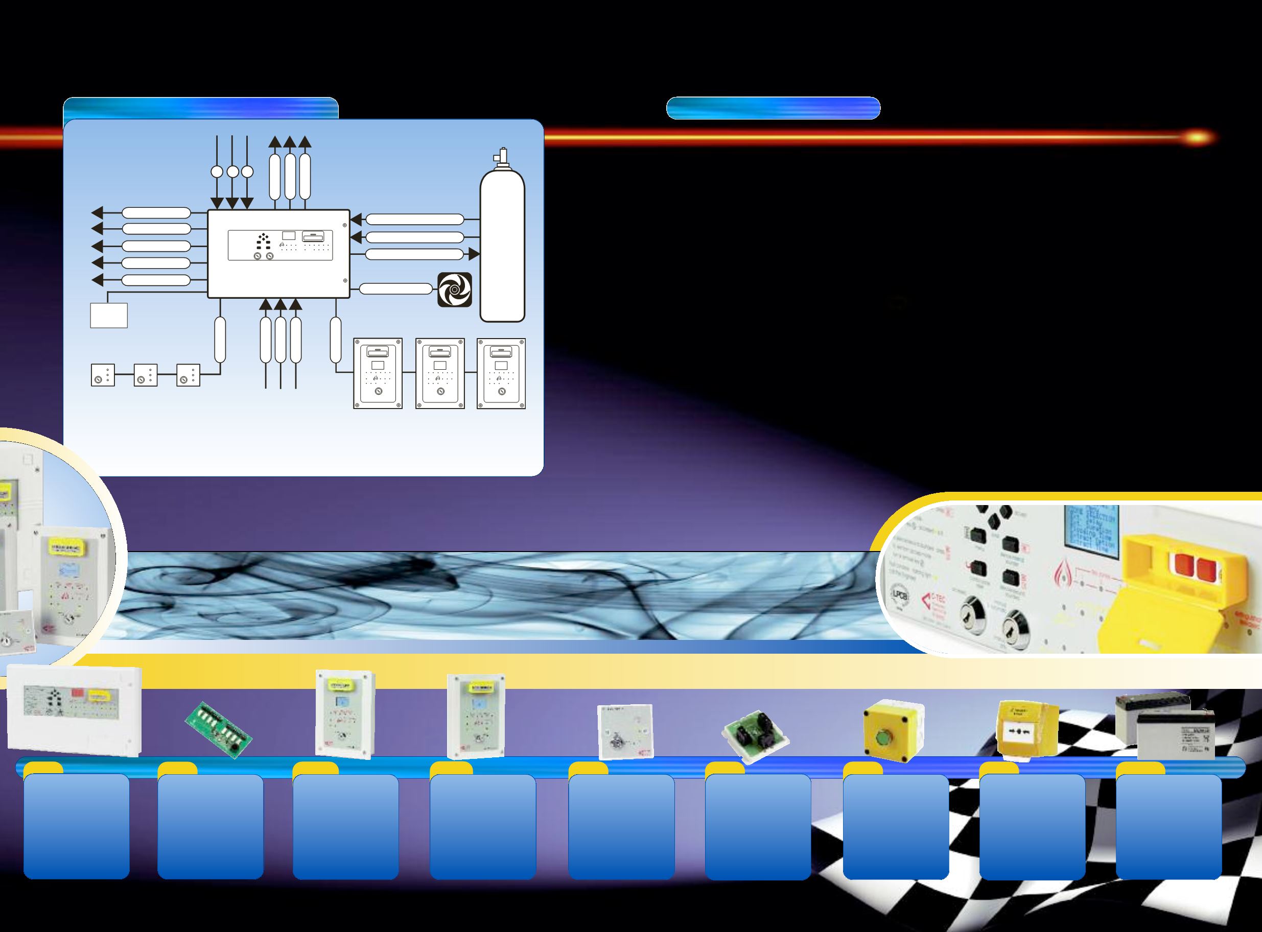
COMMISSIONING & ENGINEERING FUNCTIONS
!
Zone selection:
Selects the zone combination that starts the
extinguishant release sequence
!
Extinguishant delay:
Sets the countdown duration before extinguishant
release
!
Extinguishant duration:
Sets the duration of the firing signal to the
extinguishant output
!
Flooding time:
Sets the duration for the release of extinguishant
!
Extract option:
Enables/disables the ventilation extract option
!
Extract time:
Sets the duration for the ventilation extract fan
operation
!
Sounder delay:
Sets the delay duration before the fire sounders are
activated
!
Remote status unit learn:
Finds all remote status units and updates the panel’s
database
!
Extinguishant output EOLS:
Selects the number of extinguisher circuit terminations
!
Mode exceptions:
Selects the default setting mode when the mode input is in
Fault and/or Disabled
!
Earth fault:
Disables/enables the panel’s earth fault monitoring circuitry
!
Manual release mode:
Selects either delayed or immediate release of extinguishant
!
Zone trigger:
Enables a short circuit condition on the three detection zones
!
Clean start:
Clears the panel’s memory back to its default factory settings
!
Walk test
:
Puts detection zone(s) into walk test mode
!
Test relays:
Tests the panel’s auxiliary relay outputs
!
Test sounders:
Tests the panel’s sounder circuits
!
Monitoring:
Applies a constant monitoring voltage
!
Show PSU stats:
Displays the status of the panel’s power supply & standby
battery
EP210S
EP211
EP214
EP215
BF372
BC286/2
Output Expansion
Relay Board
Mounts inside the EP203
panel to provide volt-free
changeover relay contacts
for reset, mode, discharged,
hold and abort. Max. 1 per
EP203.
W162 x H70 x D20mm
Flush Mounting
Remote Status Unit
Includes a status LCD,
manual release and mode
(auto/manual) switches.
Max. 8 EP210F/EP210S per
EP203. Weatherproof
enclosure also available,
order code BF359/1.
W175 x H250 x D53mm
Surface Mounting
Remote Status Unit
Includes a status LCD,
manual release and mode
(auto/manual) switches.
Max. 8 EP210F/EP210S per
EP203. Weatherproof
enclosure also available,
order code BF359/1.
W160 x H240 x D51mm
Single Gang
Economy Status Unit
Includes a keyswitch
operated mode
(auto/manual) switch and
three status LEDs. Max. 8
per EP203.
W87 x H87 x D35mm
System Line
Terminator
Allows the EP203’s
extinguishant release
output to be terminated to
a gas release solenoid.
Max. 2 per EP203 (one
EP214 is supplied with the
EP203)
W55 x H55 x D22mm
Extinguishant
Hold Off/Abort Button
An IP66 rated button that
can be used to delay (hold
off) or cancel (abort) the
extinguishant release
sequence depending on
how it is connected.
W93 x H93 x D88mm
Yellow Extinguishant
Release Call Point
A surface mounting
manual call point that
can be used to remotely
trigger the EP203’s
extinguishant
release sequence
W89 x H93 x D59mm
(without cover)
24V 7.0AHr VRLA
Battery Pack
2 x 12V 7.0AHr valve
regulated lead acid
batteries and a link wire
for use as the EP203’s
standby battery supply.
W150 x H100 x D64mm (x2)
3 Zone Automatic
Extinguisher Panel
Includes all of the circuitry
for controlling the
extinguishant release, a
pull-down manual release
button, a 128x64 pixel LCD
display plus all of the
features listed left.
W467 x H293 x D100 mm