


 237 / 300

TSC-0912 - 09.10.12
IMPROVED IMPROVED IMPROVED
Furse, Wilford Road, Nottingham, NG2 1EB • Tel: +44 (0)115 964 3700 • Email:
enquiry@furse.com• Web:
www.furse.comESP KT & KE Series
Technical specification
For individual telephone lines and lines at unmanned sites the high performance ESP TN, ready-boxed derivative ESP TN/BX or ESP TN/2BX, or
plug-in ESP TN/JP or ESP TN/RJ11 Series should be used. For plug-in S/T interface ISDN protection, use the ESP TN or ISDN Series protectors.
1
Maximum working voltage (DC or AC peak) at 10 µA for
ESP KT1, ESP KT1/PTC, ESP K10T1, ESP K10T1/PTC and at
5 µA for ESP KT2 and ESP K10T2.
2
The maximum transient voltage let-through of the protector
throughout the test (±10%), line to line & line to earth, both
polarities. Response time < 10 ns.
3
Test to IEC 61000-4-5:2006, ITU-T (formerly CCITT) K.20,
K.21 and K.45,Telcordia GR-1089-CORE, Issue 2:2002,
ANSI TIA/EIA/IS-968-A:2002 (formerly FCC Part 68).
4
The installation and connections external to the protector
may limit the capability of the protector.
Electrical specification
ESP KT1
ESP KT1/PTC
ESP KT2
ESP K10T1 ESP K10T1/PTC ESP K10T2
Maximum working
- line to line
voltage
U
c
1
- line to earth
296 V
296 V
296 V
296 V
5 V
58 V
296 V
296 V
296 V
296 V
5 V
58 V
Current rating
(signal)
300 mA
145 mA
300 mA
300 mA
145 mA
300 mA
In-line resistance
(per line ±10%)
4.4
Ω
Bandwidth
(-3 dB 50
Ω
system)
> 20 MHz
> 40 MHz
> 19 MHz
> 20 MHz
> 40 MHz
> 19 MHz
Transient specification
ESP KT1
ESP KT1/PTC
ESP KT2
ESP K10T1 ESP K10T1/PTC ESP K10T2
Let-through voltage
(all conductors)
2
U
p
C2 test 4 kV 1.2/50 µs,
- line to line
2 kA 8/20 µs to
- line to earth
BS EN/EN/IEC 61643-21
395 V
395 V
395 V
395 V
28 V
88 V
395 V
395 V
395 V
395 V
28 V
88 V
C1 test 1 kV, 1.2/50 µs,
- line to line
0.5 kA 8/20 µs to
- line to earth
BS EN/EN/IEC 61643-21
390 V
390 V
390 V
390 V
23 V
63 V
390 V
390 V
390 V
390 V
23 V
63 V
B2 test 4 kV 10/700 µs to - line to line
BS EN/EN/IEC 61643-21
- line to earth
298 V
298 V
298 V
298 V
26 V
65 V
298 V
298 V
298 V
298 V
26 V
65 V
5 kV, 10/700 µs
3
- line to line
- line to earth
300 V
300 V
300 V
300 V
27 V
80 V
300 V
300 V
300 V
300 V
27 V
80 V
Maximum surge current
4
D1 test 10/350 µs to
- line to line
BS EN/EN/IEC 61643-21
- line to earth
1 kA
2 kA
8/20 µs to ITU-T K.45:2003, - line to line
IEEE C62.41.2:2002
- line to earth
5 kA
10 kA
Power faults specification
ESP KT1
ESP KT1/PTC
ESP KT2
ESP K10T1 ESP K10T1/PTC ESP K10T2
Power/Line Cross and Power Induction - tests to: ITU-T (formerly CCITT) K.20, K.21 and K.45, Telcordia GR-1089-CORE, Issue 2:2002, UL 60950/IEC 950
- power/line cross
-
110/230 Vac
(15 min)
-
-
110/230 Vac
(15 min)
-
- power induction
-
600 V, 1 A
(0.2 sec)
-
-
600 V, 1 A
(0.2 sec)
-
Mechanical specification
ESP KT1, ESP KT2,
ESP K10T1, ESP K10T2,
ESP KE10
ESP KT1/PTC
ESP K10T1/PTC
Temperature range
-40 to +80 ºC
-
Connection type
To LSA-PLUS disconnection modules (BT part number 237A)
-
Earth connection
Via ESP KE10 earth bar
Via integral earth clip/external
M4 bush
-
Material
ABS UL94 V-0
Stainless Steel
Weight -
unit
0.01 kg
0.10 kg
0.01 kg
-
packaged
0.12 kg (per 10)
0.12 kg
0.10 kg (per 10)
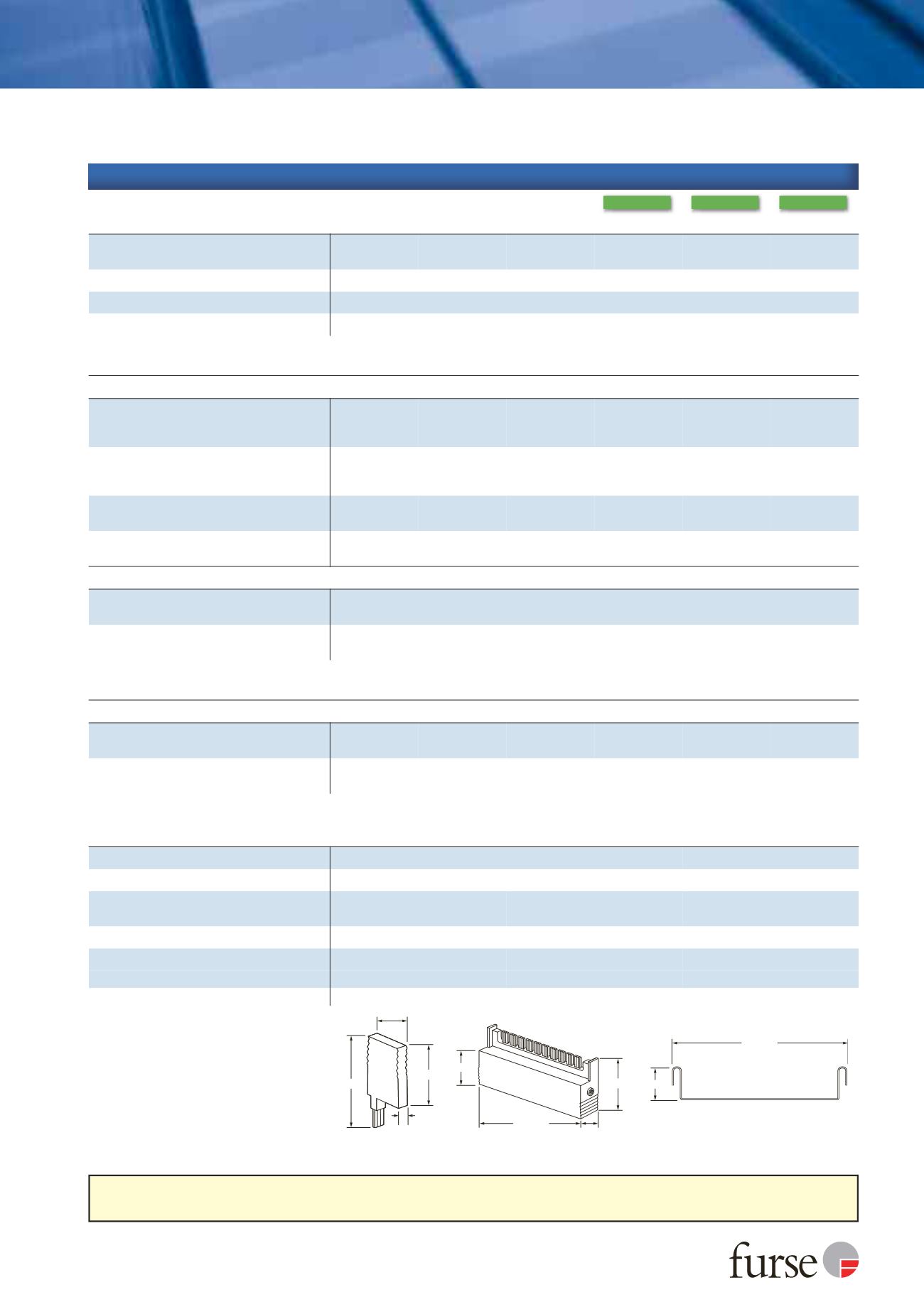
Dimensions
22 mm
Depth: 21 mm
110 mm
110 mm
22 mm
9.5 mm
52 mm
40 mm
20 mm
40 mm
59 mm