


 32 / 73

31
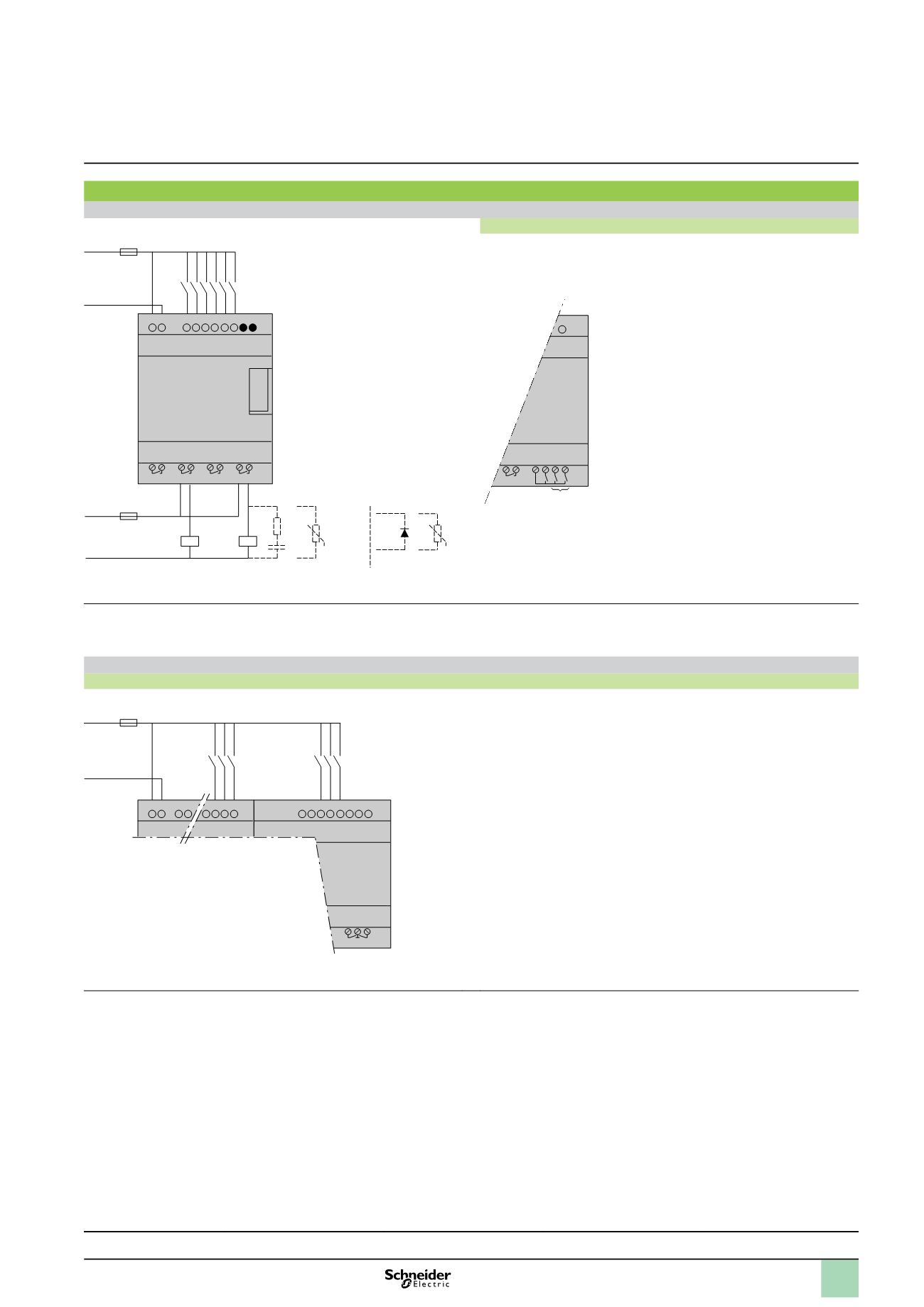
Connection of smart relays on
a
supply
SR
p ppp
1B, SR
p ppp
1FU
SR3 B261B and SR3 B261FU
(1) 1 A quick-blow fuse or circuit-breaker.
(2) Fuse or circuit-breaker.
(3) Inductive load.
(4) Q9 and QA: 5 A (max. current in terminal C: 10 A).
With discrete I/O extension module
SR3 B
ppp
B + SR3 XT
ppp
B, SR3 B
ppp
FU + SR3 XT
ppp
FU
(1) 1 A quick-blow fuse or circuit-breaker.
–
6 Q7 C Q8 Q9 QA
IA IB IC ID IE IF IG
5 A
(4)
QB QC QD QE QF QG
+ –
L
N
(1)
Module
Extension
Warning:
QF and QG: 5 A for
SR3 XT141
pp
Presentation :
pages 6 to 9
Functions :
pages 10 to 12
Characteristics :
pages 14 to 19
Curves :
pages 20 and 21
References :
pages 22 to 27
L
L N
SR
p pppp
FU
a
100…240 V
50/60 Hz
SR
p pppp
B
a
24 V
N
(1)
Q1 Q2 Q3 Q4
z
12…240 V
50/60 Hz
c
12…24 V
L /
+
N /
–
z
12…240 V
50/60 Hz
c
12…24 V
(2)
(3)
U
(3)
U
ou
Schemes
(continued)
1
Zelio Logic smart relays
1
Compact and modular smart relays
1
2
3
4
5
6
7
8
9
10