


 38 / 73

37
Parameter entry
Parameters can be entered either using “Zelio Soft 2” software, or directly using the
buttons on the Zelio Logic smart relay
(1)
.
When the “RUN” instruction is given, the Zelio Logic smart relay initialises the
Modbus network slave communication module in a configuration previously defined
in the basic program.
The Modbus slave communication module has 4 parameters:
number of UART wires and format of the frames on the Modbus network,
transmission speed,
parity,
network address of the Modbus module.
The default parameter settings are as follows: 2-wire, RTU, 19 200 bauds, even
parity, address n° 1.
b
b
b
b
Parameter entry
Options
Number of wires
2 or 4
Frame format
RTU or ASCII
Transmission speed
in bauds
1200, 2400, 4800, 9600, 19 200, 28 800, 38 400, 57 600
Parity
None, even, odd
Network address
1 to 247
Addressing of Modbus exchanges
LADDER programming
In LADDER mode, the 4 data words (16 bits) to be exchanged cannot be accessed
by the application. Transfers with the master are implicit and are effected in a way
that is totally transparent.
Modbus exchanges
Code
Number of words
Image of smart relay I/O
Read
03
4
Clock words
Read/Write
16, 06 or 03
4
Status words
Read
03
1
Function block diagram (FBD) programming
In FBD mode, the 4 input data words (16 bits) (J1XT1 to J4XT1) and the 4 output
data words (O1XT1 to O4XT1) can be accessed by the application. Dedicated
function blocks make it possible to:
break down a ‘complete’ type input (16 bits) into 16 separate “bit” type outputs.
example: break down a J1XT1 to J4XT1 type input and copy these status values
to discrete outputs.
make up a ‘complete’ type output (16 bits) from 16 separate “bit” type inputs.
example: transfer the status value of the discrete inputs or the status of a function
to an O1XT1 to O4XT1 type output.
b
v
b
v
Modbus exchanges
Code
Number of words
Input words
Read/Write
16, 06 or 03
4
Output words
Read
03
4
Clock words
Read/Write
16, 06 or 03
4
Status words
Read
03
1
(1) Programming from the front panel and buttons on the smart relay is only possible in
LADDER language.
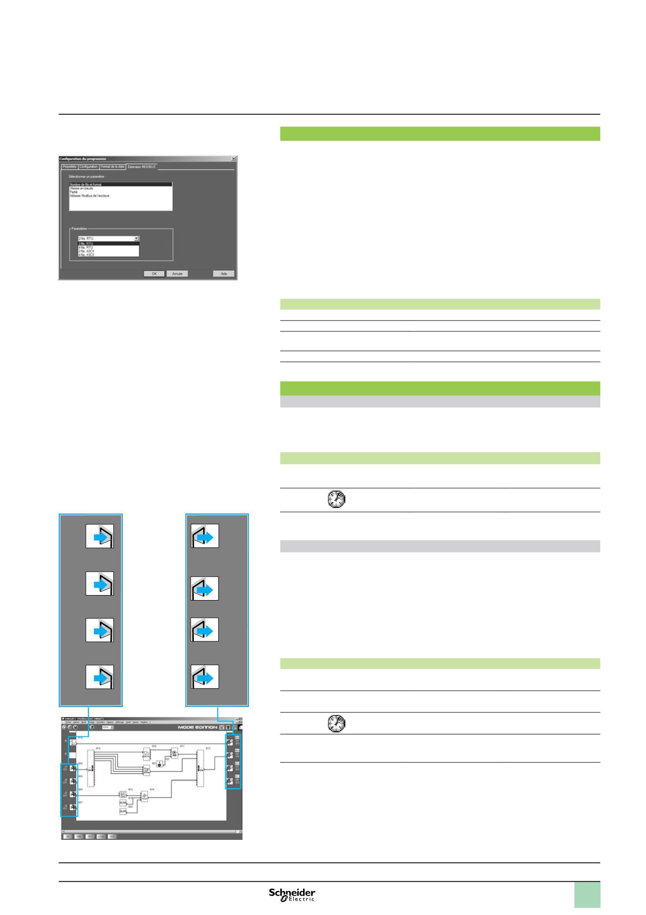
Software workshop
parameter entry window
J1
XT1
J2
XT1
J3
XT1
J4
XT1
3
7
2
3
7
2
3
7
2
3
7
2
01
XT1
02
XT1
03
XT1
04
XT1
0
9
3
4
0
9
3
4
0
9
3
4
0
9
3
4
Presentation, description :
pages 34 and 35
Characteristics :
page 36
References :
page 42
Dimensions, mounting :
page 43
524121
524110
Input words
Output words
FDB program Editing window
Functions
1
Zelio Logic smart relays
1
Communication
Modbus slave communication protocol
1
2
3
4
5
6
7
8
9
10