


 95 / 338

A-43
Compact INS-INV630b to 1600
Compact INS-INV2000-2500
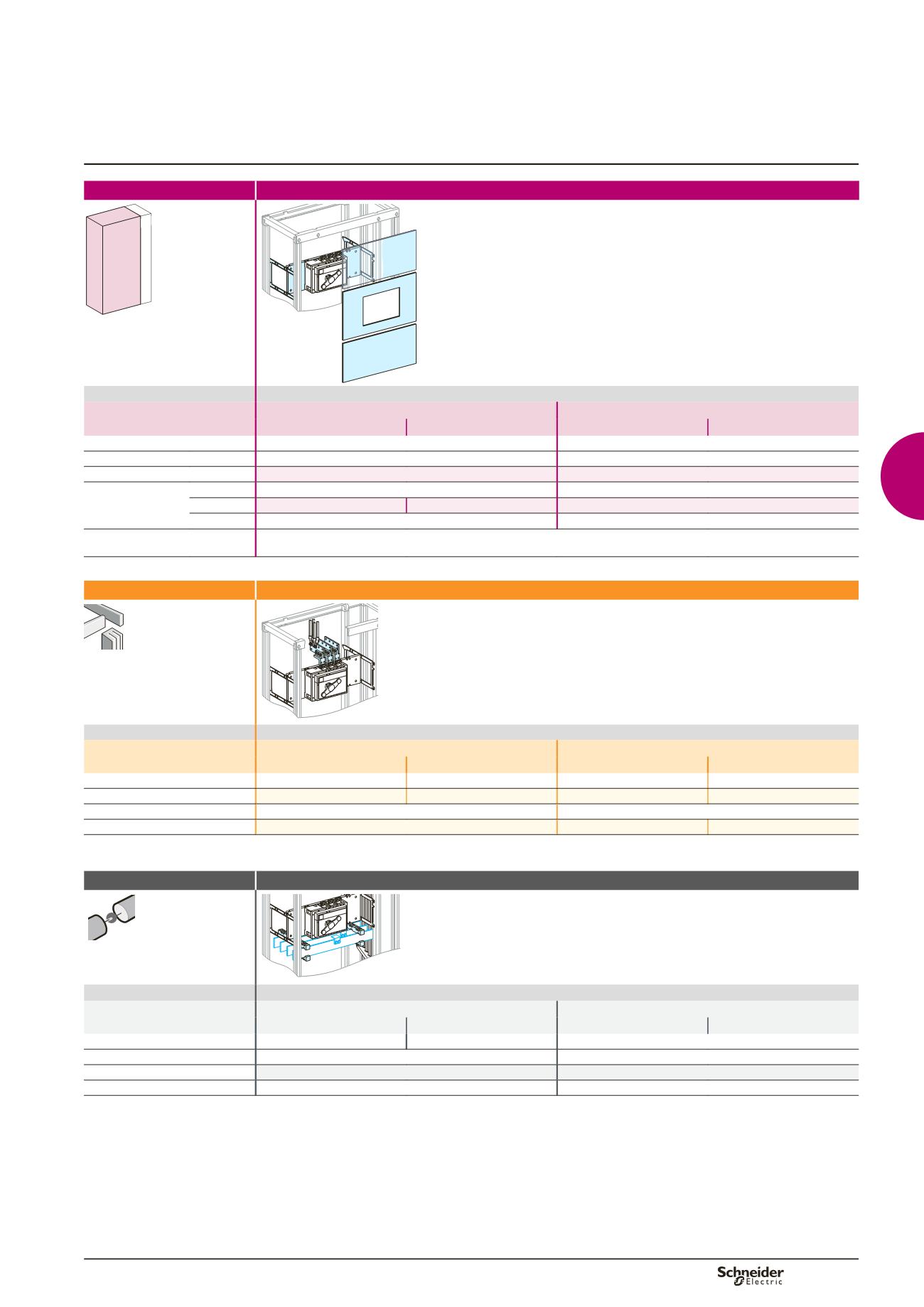
Functional system
Functional units
Switch disconnectors
Mounting
Vertical fixed
650 150
400
Dd383581.eps
Devices
Fixed device
INS-INV630b/1600
INS-INV2000/2500
3P
4P
3P
4P
Number of devices per row
1
1
No. of vertical modules
14
16
Mounting plates
03501
03501
Front plates
[No. of vertical
modules]
upstream
03804
[4]
03803
[3]
with cut-out
03713
[6]
03714
[6]
03715
[10]
downstream
03804
[4]
03803
[3]
Characteristics
Depending on the type of front connection, an INS-INV2000-2500 can be mounted in a 400 mm or 600 mm deep enclosure.
For rear connection, a 600 mm deep enclosure is required.
Connection
With cable
Dd383580.eps
Devices
Fixed device
INS-INV630b/1600
INS-INV2000/2500
3P
4P
3P
4P
Vertical connection adapters
31301
(1)
31302
(1)
33975
(1)
33976
(1)
Cable-lug adapters
33644
(1)
33645
(1)
-
-
Connection
-
must be made
Terminal extension bar support
-
04694
04694
(1)
Vertical connection adapters and cable-lug adapters are not compatible with input voltage
u
500 V.
Distribution
Connection with cable
Dd383582.eps
Devices
Fixed device
INS-INV630b/1600
INS-INV2000/2500
3P
4P
3P
4P
Connection LGY
04481
04482
must be made
Connection BS, LGYE
must be made
must be made
Cover for busbars connection
04926
(2)
04926
(2)
Free support
-
2 x
04662
(2)
Partitioning of devices must be made.
Selection of Linergy LGY:
see page B-14,
Linergy LGYE:
see page B-15,
Linergy BS:
see page B-16.